 |
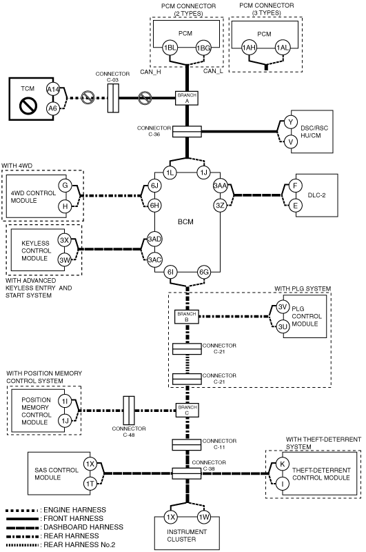
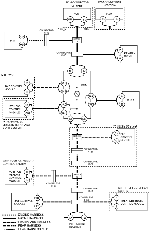
ac9wzw00001804
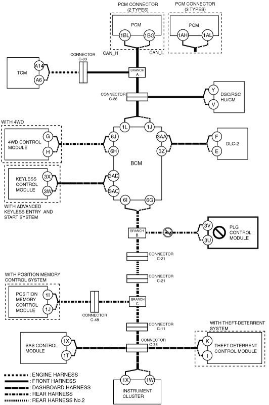
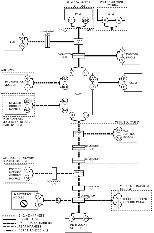
DETERMINING MALFUNCTIONING PART (HS-CAN) [MULTIPLEX COMMUNICATION SYSTEM (L.H.D.)]
id0902j3846700
1. Verify the CAN system-related module DTCs and the failed module using the (M-MDS).
2. Look for a DTC display pattern and failed module display pattern in tandem which match.
3. Refer to the matching tandem diagnostic results (A to Q) and inspect the possible cause and inspection item.
4. Perform the DTC inspection after the repair procedure.
Diagnostic Table for Determining Malfunctioning Part
|
M-MDS display
|
DTC display pattern
|
|||||||||||||||||
|
DTC output module
|
DTC
|
|||||||||||||||||
|
PCM
(PCM*1)
|
U0101
|
|
×
|
|
|
|
|
|
|
|
|
|
|
|
|
|
|
|
|
U0129
|
|
|
|
×
|
|
|
|
|
|
|
|
|
|
|
|
|
|
|
|
U0155
|
|
|
|
|
|
|
|
|
|
|
|
|
|
|
|
|
×
|
|
|
PCM
(PCM*2)
|
U0101:00
|
|
×
|
|
|
|
|
|
|
|
|
|
|
|
|
|
|
|
|
U0140:00
|
|
|
|
|
|
×
|
|
|
|
|
|
|
|
|
|
|
|
|
|
TCM
(TCM*3)
|
U0100
|
×
|
|
|
|
|
|
|
|
|
|
|
|
|
|
|
|
|
|
U0121
|
|
|
|
×
|
|
|
|
|
|
|
|
|
|
|
|
|
|
|
|
U0140
|
|
|
|
|
|
×
|
|
|
|
|
|
|
|
|
|
|
|
|
|
U0415
|
|
|
|
-
|
|
|
|
|
|
|
|
|
|
|
|
|
|
|
|
TCM
(TCM*4)
|
U0100:00
|
×
|
|
|
|
|
|
|
|
|
|
|
|
|
|
|
|
|
|
U0121:00
|
|
|
|
×
|
|
|
|
|
|
|
|
|
|
|
|
|
|
|
|
U0155:00
|
|
|
|
|
|
|
|
|
|
|
|
|
|
|
|
|
×
|
|
|
U0415:00
|
|
|
|
-
|
|
|
|
|
|
|
|
|
|
|
|
|
|
|
|
ABS
(DSC/RSC HU/CM)
|
U0100
|
×
|
|
×
|
|
|
|
|
|
|
|
|
|
|
|
|
|
|
|
U0140
|
|
|
|
|
|
×
|
|
|
|
|
|
|
|
|
|
|
|
|
|
U0155
|
|
|
|
|
|
|
|
|
|
|
|
|
|
|
|
|
×
|
|
|
GEM
(BCM)
|
U0100
|
×
|
|
×
|
|
×
|
|
|
|
|
|
|
|
|
|
|
|
|
|
U0101
|
|
×
|
×
|
|
×
|
|
|
|
|
|
|
|
|
|
|
|
|
|
|
U0121
|
|
|
|
×
|
×
|
|
|
|
|
|
|
|
|
|
|
|
|
|
|
U0401
|
-
|
|
-
|
|
-
|
|
|
|
|
|
|
|
|
|
|
|
|
|
|
4×4*5
(4WD control module)
|
U0100
|
×
|
|
×
|
|
×
|
|
|
|
|
|
|
|
|
|
|
|
|
|
U0101
|
|
×
|
×
|
|
×
|
|
|
|
|
|
|
|
|
|
|
|
|
|
|
U0121
|
|
|
|
×
|
×
|
|
|
|
|
|
|
|
|
|
|
|
|
|
|
U0155
|
|
|
|
|
|
|
|
|
|
|
|
|
|
|
|
|
×
|
|
|
RKE*6
(Keyless control module)
|
U0100
|
×
|
|
×
|
|
×
|
|
|
×
|
|
|
|
|
|
|
|
|
|
|
U0140
|
|
|
|
|
|
×
|
|
×
|
|
|
|
|
|
|
|
|
|
|
|
U0323
|
|
|
|
|
|
|
|
|
|
|
|
|
|
|
|
|
×
|
|
|
U2023
|
-
|
|
-
|
|
-
|
|
|
-
|
|
|
|
|
|
|
|
|
|
|
|
LTM*7
(PLG control module)
|
U0100
|
×
|
|
×
|
|
×
|
|
|
×
|
|
×
|
|
|
|
|
|
|
|
|
U0101
|
|
×
|
×
|
|
×
|
|
|
×
|
|
×
|
|
|
|
|
|
|
|
|
|
U0140
|
|
|
|
|
|
×
|
|
×
|
|
×
|
|
|
|
|
|
|
|
|
|
U0155
|
|
|
|
|
|
|
|
|
|
|
|
|
|
|
|
|
×
|
|
|
U0214
|
|
|
|
|
|
|
|
|
×
|
×
|
|
|
|
|
|
|
|
|
|
DSM*8
(Position memory control module)
|
U0100:00
|
×
|
|
×
|
|
×
|
|
|
×
|
|
×
|
|
×
|
|
|
|
|
|
|
U0101:00
|
|
×
|
×
|
|
×
|
|
|
×
|
|
×
|
|
×
|
|
|
|
|
|
|
|
U0121:00
|
|
|
|
×
|
×
|
|
|
×
|
|
×
|
|
×
|
|
|
|
|
|
|
|
U0140:00
|
|
|
|
|
|
×
|
|
×
|
|
×
|
|
×
|
|
|
|
|
|
|
|
U0155:00
|
|
|
|
|
|
|
|
|
|
|
|
|
|
|
|
|
×
|
|
|
U0431:68
|
|
|
|
|
|
-
|
|
-
|
|
-
|
|
-
|
|
|
|
|
|
|
|
RCM
(SAS control module)
|
U0155
|
|
|
|
|
|
|
|
|
|
|
|
|
|
|
|
|
×
|
|
VSM*9
(Theft-deterrent control module)
|
U0100:00
|
×
|
|
×
|
|
×
|
|
|
×
|
|
×
|
|
×
|
|
×
|
|
|
|
|
U0140:00
|
|
|
|
|
|
×
|
|
×
|
|
×
|
|
×
|
|
×
|
|
|
|
|
|
IC
(Instrument cluster)
|
U0100
|
×
|
|
×
|
|
×
|
|
|
×
|
|
×
|
|
×
|
|
×
|
|
|
|
|
U0101
|
|
×
|
×
|
|
×
|
|
|
×
|
|
×
|
|
×
|
|
×
|
|
|
|
|
|
U0114
|
|
|
|
|
|
|
×
|
×
|
|
×
|
|
×
|
|
×
|
|
|
|
|
|
U0121
|
|
|
|
×
|
×
|
|
|
×
|
|
×
|
|
×
|
|
×
|
|
|
|
|
|
U0140
|
|
|
|
|
|
×
|
|
×
|
|
×
|
|
×
|
|
×
|
|
|
|
|
|
U0151
|
|
|
|
|
|
|
|
|
|
|
|
|
|
|
×
|
|
|
|
|
U0214
|
|
|
|
|
|
|
|
|
×
|
×
|
|
×
|
|
×
|
|
|
|
|
|
U2510
|
-
|
|
-
|
|
-
|
|
|
-
|
|
-
|
|
-
|
|
-
|
|
|
|
|
|
M-MDS display module
|
“Fail” display pattern
|
|||||||||||||||||
|
PCM
|
×
|
|
×
|
|
×
|
|
|
×
|
|
×
|
|
×
|
|
×
|
|
|
|
|
|
TCM
|
|
×
|
×
|
|
×
|
|
|
×
|
|
×
|
|
×
|
|
×
|
|
|
|
|
|
ABS
|
|
|
|
×
|
×
|
|
|
×
|
|
×
|
|
×
|
|
×
|
|
|
|
|
|
GEM
|
|
|
|
|
|
×
|
|
×
|
|
×
|
|
×
|
|
×
|
|
|
|
|
|
4×45
|
|
|
|
|
|
|
×
|
×
|
|
×
|
|
×
|
|
×
|
|
|
|
|
|
RKE*6
|
|
|
|
|
|
|
|
|
×
|
×
|
|
×
|
|
×
|
|
|
|
|
|
LTM*7
|
|
|
|
|
|
|
|
|
|
|
×
|
×
|
|
×
|
|
|
|
|
|
DSM*8
|
|
|
|
|
|
|
|
|
|
|
|
|
×
|
×
|
|
|
|
|
|
RCM
|
|
|
|
|
|
|
|
|
|
|
|
|
|
|
×
|
|
|
|
|
VSM*9
|
|
|
|
|
|
|
|
|
|
|
|
|
|
|
|
×
|
|
|
|
IC
|
|
|
|
|
|
|
|
|
|
|
|
|
|
|
|
|
×
|
|
|
Item
|
Diagnostic result
|
|||||||||||||||||
|
Possible cause and inspection item
|
A
|
B
|
C
|
D
|
E
|
F
|
G
|
H
|
I
|
J
|
K
|
L
|
M
|
N
|
O
|
P
|
Q
|
|
|
Reference page
|
||||||||||||||||||
A
Possible cause
System wiring diagram
ac9wzw00001804
|
Inspection item
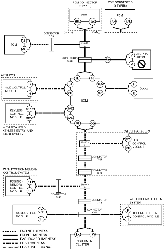
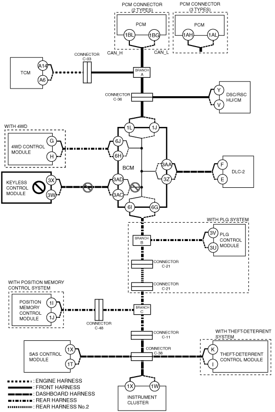
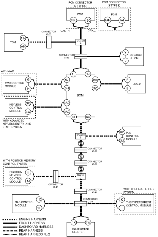
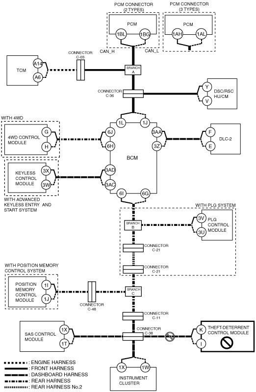
B
Possible cause
System wiring diagram
ac9wzw00001805
|
Inspection item
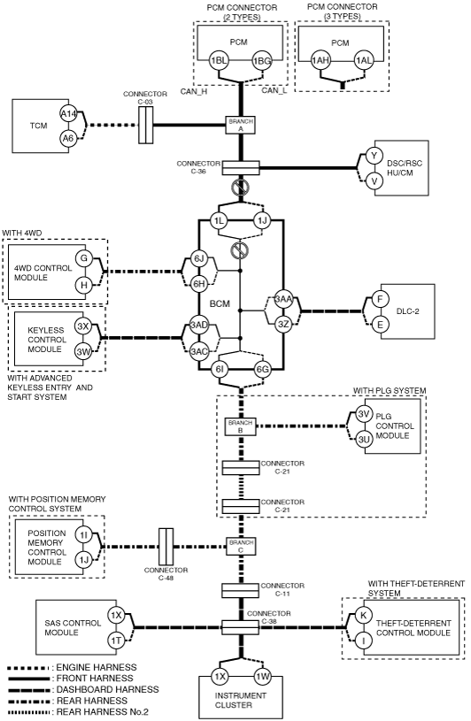
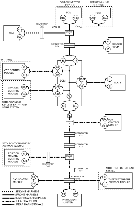
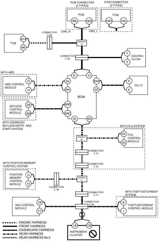
C
Possible cause
System wiring diagram
ac9wzw00001806
|
Inspection item
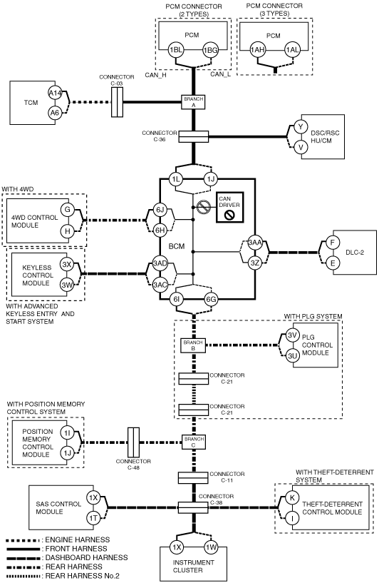
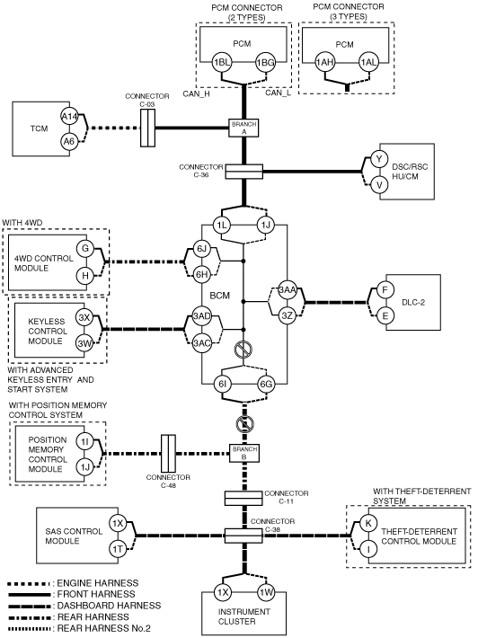
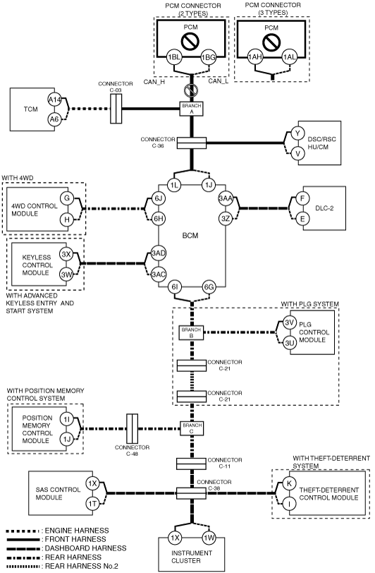
D
Possible cause
System wiring diagram
ac9wzw00001807
|
Inspection item
E
Possible cause
System wiring diagram
ac9wzw00001808
|
Inspection item
F
Possible cause
System wiring diagram
ac9wzw00001809
|
Inspection item
G
Possible cause
System wiring diagram
ac9wzw00001810
|
Inspection item
H
Possible cause
System wiring diagram
ac9wzw00001811
|
Inspection item
I
Possible cause
System wiring diagram
ac9wzw00001812
|
Inspection item
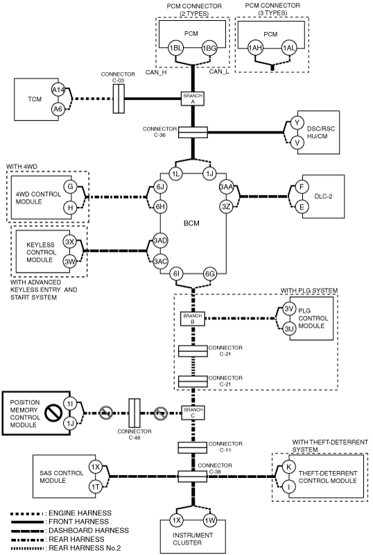
J
With PLG system
System wiring diagram
ac9wzw00001813
|
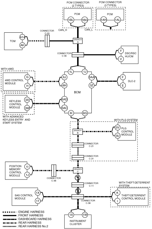
Without PLG system
System wiring diagram
ac9wzw00001814
|
K
Possible cause
System wiring diagram
ac9wzw00001815
|
Inspection item
L
Possible cause
System wiring diagram
ac9wzw00001816
|
Inspection item
M
Possible cause
System wiring diagram
ac9wzw00001817
|
Inspection item
N
Possible cause
System wiring diagram
ac9wzw00001818
|
Inspection item
O
Possible cause
System wiring diagram
ac9wzw00001819
|
Inspection item
P
Possible cause
System wiring diagram
ac9wzw00001820
|
Inspection item
Q
Possible cause
System wiring diagram
ac9wzw00001821
|
Inspection item