 |
ac9wzw00001831
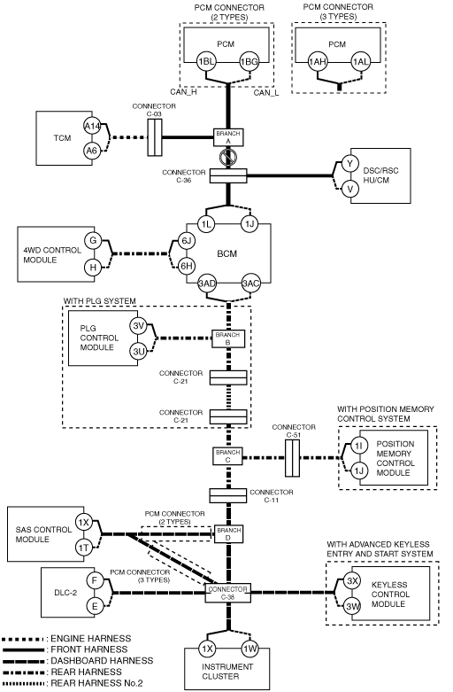
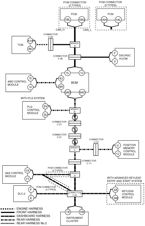
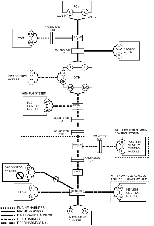
DETERMINING MALFUNCTIONING PART (HS-CAN) [MULTIPLEX COMMUNICATION SYSTEM (R.H.D.)]
id0902j4846700
1. Verify the CAN system-related module DTCs and the failed module using the (M-MDS).
2. Look for a DTC display pattern and failed module display pattern in tandem which match.
3. Refer to the matching tandem diagnostic results (A to P) and inspect the possible cause and inspection item.
4. Perform the DTC inspection after the repair procedure.
Diagnostic Table for Determining Malfunctioning Part
|
M-MDS display
|
DTC display pattern
|
||||||||||||||||
|
DTC output module
|
DTC
|
||||||||||||||||
|
PCM
(PCM*1)
|
U0101
|
|
×
|
|
|
|
|
|
|
|
|
|
|
|
|
|
|
|
U0129
|
|
|
|
×
|
|
|
|
|
|
|
|
|
|
|
|
|
|
|
U0155
|
|
|
|
|
|
|
|
|
|
|
|
|
|
|
|
×
|
|
|
PCM
(PCM*2)
|
U0101:00
|
|
×
|
|
|
|
|
|
|
|
|
|
|
|
|
|
|
|
U0140:00
|
|
|
|
|
|
×
|
|
|
|
|
|
|
|
|
|
|
|
|
TCM
(TCM*3)
|
U0100
|
×
|
|
|
|
|
|
|
|
|
|
|
|
|
|
|
|
|
U0121
|
|
|
|
×
|
|
|
|
|
|
|
|
|
|
|
|
|
|
|
U0140
|
|
|
|
|
|
×
|
|
|
|
|
|
|
|
|
|
|
|
|
U0415
|
|
|
|
-
|
|
|
|
|
|
|
|
|
|
|
|
|
|
|
TCM
(TCM*4)
|
U0100:00
|
×
|
|
|
|
|
|
|
|
|
|
|
|
|
|
|
|
|
U0121:00
|
|
|
|
×
|
|
|
|
|
|
|
|
|
|
|
|
|
|
|
U0155:00
|
|
|
|
|
|
|
|
|
|
|
|
|
|
|
|
×
|
|
|
U0415:00
|
|
|
|
-
|
|
|
|
|
|
|
|
|
|
|
|
|
|
|
ABS
(DSC/RSC HU/CM)
|
U0100
|
×
|
|
×
|
|
|
|
|
|
|
|
|
|
|
|
|
|
|
U0140
|
|
|
|
|
|
×
|
|
|
|
|
|
|
|
|
|
|
|
|
U0155
|
|
|
|
|
|
|
|
|
|
|
|
|
|
|
|
×
|
|
|
GEM
(BCM)
|
U0100
|
×
|
|
×
|
|
×
|
|
|
|
|
|
|
|
|
|
|
|
|
U0101
|
|
×
|
×
|
|
×
|
|
|
|
|
|
|
|
|
|
|
|
|
|
U0121
|
|
|
|
×
|
×
|
|
|
|
|
|
|
|
|
|
|
|
|
|
U0401
|
-
|
|
-
|
|
-
|
|
|
|
|
|
|
|
|
|
|
|
|
|
4×4*5
(4WD control module)
|
U0100
|
×
|
|
×
|
|
×
|
|
|
|
|
|
|
|
|
|
|
|
|
U0101
|
|
×
|
×
|
|
×
|
|
|
|
|
|
|
|
|
|
|
|
|
|
U0121
|
|
|
|
×
|
×
|
|
|
|
|
|
|
|
|
|
|
|
|
|
U0155
|
|
|
|
|
|
|
|
|
|
|
|
|
|
|
|
×
|
|
|
LTM*6
(PLG control module)
|
U0100
|
×
|
|
×
|
|
×
|
|
|
×
|
|
|
|
|
|
|
|
|
|
U0101
|
|
×
|
×
|
|
×
|
|
|
×
|
|
|
|
|
|
|
|
|
|
|
U0140
|
|
|
|
|
|
×
|
|
×
|
|
|
|
|
|
|
|
|
|
|
U0155
|
|
|
|
|
|
|
|
|
|
|
|
|
|
|
|
×
|
|
|
U0214
|
|
|
|
|
|
|
|
|
|
|
|
|
|
|
×
|
|
|
|
DSM*7
(Position memory control module)
|
U0100:00
|
×
|
|
×
|
|
×
|
|
|
×
|
|
×
|
|
|
|
|
|
|
|
U0101:00
|
|
×
|
×
|
|
×
|
|
|
×
|
|
×
|
|
|
|
|
|
|
|
|
U0121:00
|
|
|
|
×
|
×
|
|
|
×
|
|
×
|
|
|
|
|
|
|
|
|
U0140:00
|
|
|
|
|
|
×
|
|
×
|
|
×
|
|
|
|
|
|
|
|
|
U0155:00
|
|
|
|
|
|
|
|
|
|
|
|
|
|
|
|
×
|
|
|
U0431:68
|
|
|
|
|
|
-
|
|
-
|
|
-
|
|
|
|
|
|
|
|
|
RCM
(SAS control module)
|
U0155
|
|
|
|
|
|
|
|
|
|
|
|
|
|
|
|
×
|
|
RKE*8
(Keyless control module)
|
U0100
|
×
|
|
×
|
|
×
|
|
|
×
|
|
×
|
|
×
|
|
×
|
|
|
|
U0140
|
|
|
|
|
|
×
|
|
×
|
|
×
|
|
×
|
|
×
|
|
|
|
|
U0323
|
|
|
|
|
|
|
|
|
|
|
|
|
|
|
|
×
|
|
|
U2023
|
-
|
|
-
|
|
-
|
|
|
-
|
|
-
|
|
-
|
|
-
|
|
|
|
|
IC
(Instrument cluster)
|
U0100
|
×
|
|
×
|
|
×
|
|
|
×
|
|
×
|
|
×
|
|
×
|
|
|
|
U0101
|
|
×
|
×
|
|
×
|
|
|
×
|
|
×
|
|
×
|
|
×
|
|
|
|
|
U0114
|
|
|
|
|
|
|
×
|
×
|
|
×
|
|
×
|
|
×
|
|
|
|
|
U0121
|
|
|
|
×
|
×
|
|
|
×
|
|
×
|
|
×
|
|
×
|
|
|
|
|
U0140
|
|
|
|
|
|
×
|
|
×
|
|
×
|
|
×
|
|
×
|
|
|
|
|
U0151
|
|
|
|
|
|
|
|
|
|
|
|
|
×
|
×
|
|
|
|
|
U0214
|
|
|
|
|
|
|
|
|
|
|
|
|
|
|
×
|
|
|
|
U2510
|
-
|
|
-
|
|
-
|
|
|
-
|
|
-
|
|
-
|
|
-
|
|
|
|
|
M-MDS display module
|
“Fail” display pattern
|
||||||||||||||||
|
PCM
|
×
|
|
×
|
|
×
|
|
|
×
|
|
×
|
|
×
|
|
×
|
|
|
|
|
TCM
|
|
×
|
×
|
|
×
|
|
|
×
|
|
×
|
|
×
|
|
×
|
|
|
|
|
ABS
|
|
|
|
×
|
×
|
|
|
×
|
|
×
|
|
×
|
|
×
|
|
|
|
|
GEM
|
|
|
|
|
|
×
|
|
×
|
|
×
|
|
×
|
|
×
|
|
|
|
|
4×4*5
|
|
|
|
|
|
|
×
|
×
|
|
×
|
|
×
|
|
×
|
|
|
|
|
LTM*6
|
|
|
|
|
|
|
|
|
×
|
×
|
|
×
|
|
×
|
|
|
|
|
DSM*7
|
|
|
|
|
|
|
|
|
|
|
×
|
×
|
|
×
|
|
|
|
|
RCM
|
|
|
|
|
|
|
|
|
|
|
|
|
×
|
×
|
|
|
|
|
RKE*8
|
|
|
|
|
|
|
|
|
|
|
|
|
|
|
×
|
|
|
|
IC
|
|
|
|
|
|
|
|
|
|
|
|
|
|
|
|
×
|
|
|
Item
|
Diagnostic result
|
||||||||||||||||
|
Possible cause and inspection item
|
A
|
B
|
C
|
D
|
E
|
F
|
G
|
H
|
I
|
J
|
K
|
L
|
M
|
N
|
O
|
P
|
|
|
Reference page
|
|||||||||||||||||
A
Possible cause
System wiring diagram
ac9wzw00001831
|
Inspection item
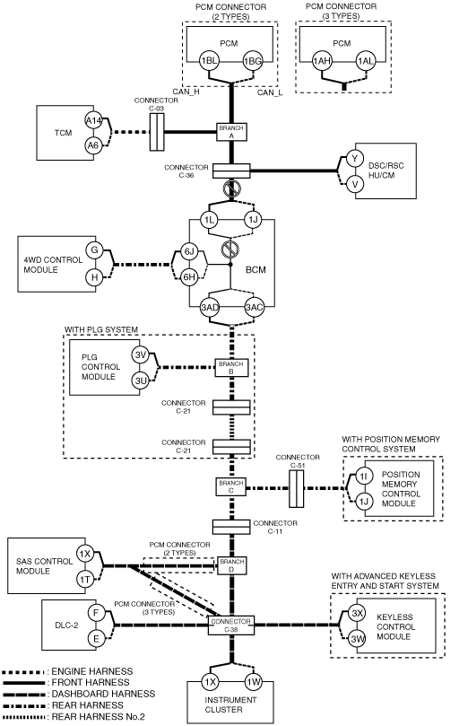
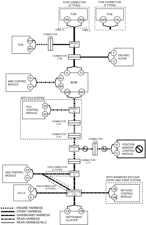
B
Possible cause
System wiring diagram
ac9wzw00001832
|
Inspection item
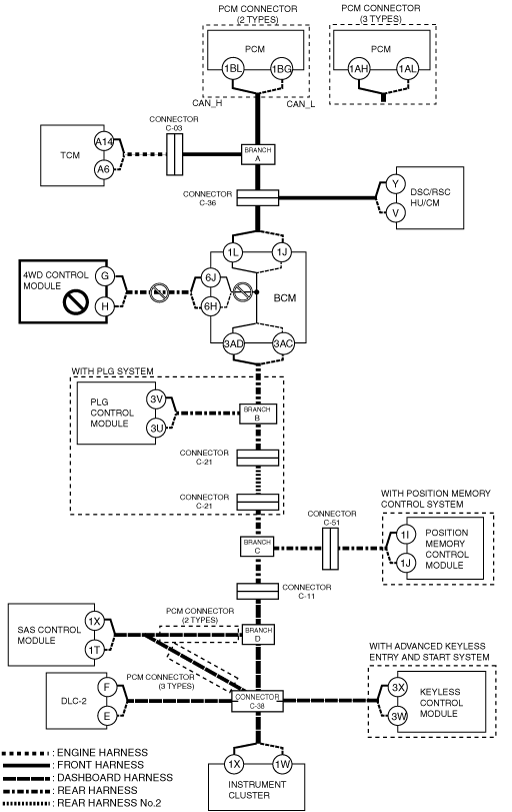
C
Possible cause
System wiring diagram
ac9wzw00001833
|
Inspection item
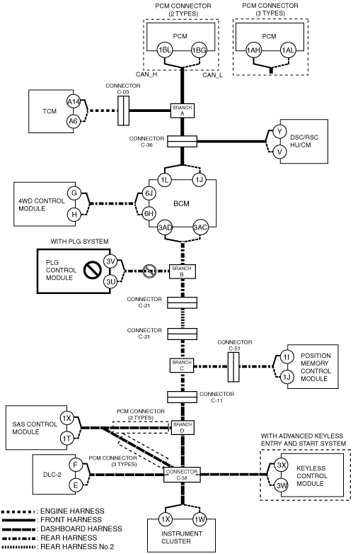
D
Possible cause
System wiring diagram
ac9wzw00001834
|
Inspection item
E
Possible cause
System wiring diagram
ac9wzw00001835
|
Inspection item
F
Possible cause
System wiring diagram
ac9wzw00001836
|
Inspection item
G
Possible cause
System wiring diagram
ac9wzw00001837
|
Inspection item
H
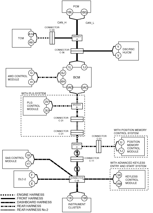
With PLG system
System wiring diagram
ac9wzw00001838
|
Without PLG system
System wiring diagram
ac9wzw00001839
|
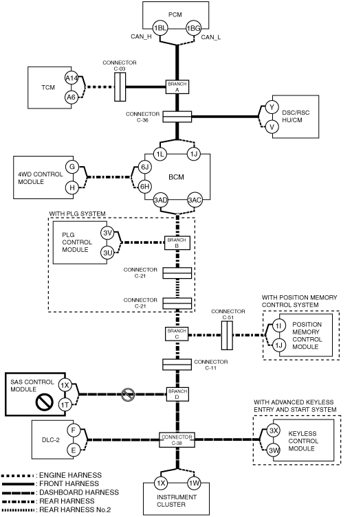
I
Possible cause
System wiring diagram
ac9wzw00001840
|
Inspection item
J
Possible cause
System wiring diagram
ac9wzw00001841
|
Inspection item
K
Possible cause
System wiring diagram
ac9wzw00001842
|
Inspection item
L
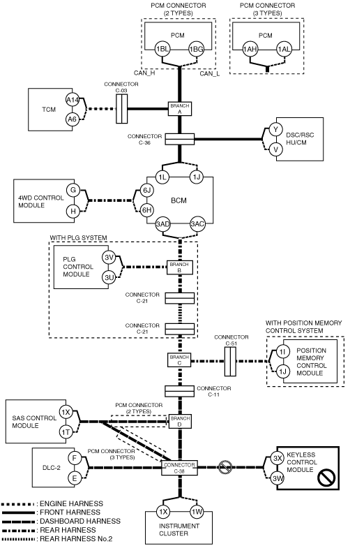
PCM connector (2 types)
System wiring diagram
ac9wzw00001843
|
PCM connector (3 types)
System wiring diagram
ac9wzw00001844
|
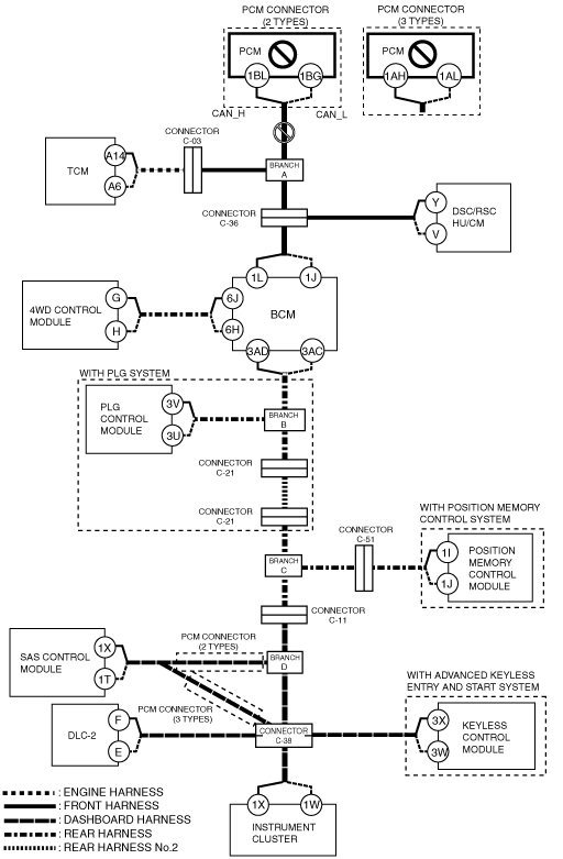
M
PCM connector (2 types)
System wiring diagram
ac9wzw00001845
|
PCM connector (3 types)
System wiring diagram
ac9wzw00001846
|
N
Possible cause
System wiring diagram
ac9wzw00001847
|
Inspection item
O
Possible cause
System wiring diagram
ac9wzw00001848
|
Inspection item
P
Possible cause
System wiring diagram
ac9wzw00001849
|
Inspection item