|
1
|
• Retrieve the advanced keyless system DTC using the M-MDS.
• Are there DTC displayed?
|
Yes
|
Perform the applicable DTC diagnostic procedures.
|
|
No
|
Go to the next step.
|
|
2
|
• Did the customer attempt to operate each front doors and liftgate using the request switch?
|
Yes
|
Go to the next step.
|
|
No
|
Inspect the advanced keyless system operations using the request switch. If the advanced keyless system is inoperative, then go to the next step.
|
|
3
|
• Prepare the followings:
-
― Make sure that there is no transmitter (advanced key) inside the passenger compartment.
― Close all doors including liftgate.
― Remove the key from the steering lock.
― Make sure that start knob is to the LOCK position. (Do not Press the knob)
― Make sure that the transmitter (advanced key) is within the advanced keyless system operative area (within 80 cm {2.6 ft} from front door)
• Does the advanced keyless system operate properly?
|
Yes
|
The system is normal. Explain the advanced keyless system operation.
|
|
No
|
Go to the next step.
|
|
4
|
• Replace with a transmitter (advanced key) battery known to be good.
• Operate the transmitter (advanced key).
• Does the keyless entry system operate properly?
|
Yes
|
Replace the transmitter (advanced key). Then go to the next step.
|
|
No
|
Go to the next step.
|
|
5
|
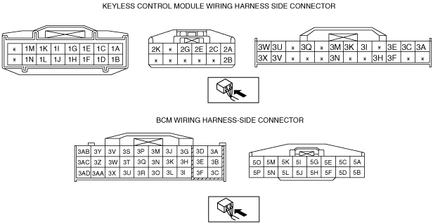
• Measure the voltage at the keyless control module terminals 3K, 3I and 3M while operating the request switch.
-
― Operate front door request switch (LF) 3K: 5.0 V→1.0 V or less
― Operate front door request switch (RF) 3I: 5.0 V→1.0 V or less
― Operate liftgate request switch (3M): 5.0 V→1.0 V or less
• Is the voltage as above?
|
Yes
|
Go to the next step.
|
|
No
|
Inspect and repair the applicable wiring harness as necessary, then go to the next step.
|
|
6
|
• Turn the start knob to LOCK position with mechanical key is not in ignition switch, and the start knob is not pushed.
• Measure the voltage following keyless control module connector.
-
― Terminal 3F (keyless switch): below 1.0 V
― Terminal 3E (start knob (push switch)): below 1.0 V
― Terminal 2E (ACC voltage): below 1.0 V
― Terminal 2C (IG1 voltage): below 1.0 V
• Is the signal voltage normal?
|
Yes
|
Go to the next step.
|
|
No
|
Inspect and repair for open or short circuit in wiring between the suspect switch and keyless control module, then go to the next step.
|
|
7
|
• Measure the pulse profile using an oscilloscope at following keyless control module terminal (52-pin).
-
― Terminal 1A for exterior, RF keyless antenna
― Terminal 1C for exterior, LF keyless antenna
― Terminal 1E for exterior, rear keyless antenna
― Terminal 1I for interior, rear keyless antenna
― Terminal 1K for interior, middle keyless antenna
― Terminal 1M for interior, front center keyless antenna
• Compare the pulse signal generating frequency between advanced key in communication areas and out of it.
• Is the pulse signal generating frequency at advanced key in communication areas become longer than out of it?
-
Note
-
• The pulse signal generating frequency at advanced key in communication areas twice as longer than out of it.
|
Yes
|
Go to the next step.
|
|
No
|
• Inspect for open or short circuit between suspect keyless antenna and keyless control module.
-
― If the wiring harness normal, replace suspect keyless antenna, then go to the next step.
― If the wiring harness is not normal, repair or replace for open or short circuit, then go to the next step.
|
|
8
|
• Measure the pulse profile using an oscilloscope at the keyless control module terminal 3C while operating the transmitter (advanced key).
• Is the pulse profile become long at moment of transmitter operation?
|
Yes
|
Go to the next step.
|
|
No
|
• Inspect the wiring harness between the keyless receiver and the keyless control module.
-
― If the harness is normal, replace the keyless receiver.
― If the harness is malfunctioning, repair the wiring harness.
• Go to the next step.
|
|
9
|
• Inspect for open or short circuit between keyless control module terminal 3Q terminal and BCM terminal 3B.
• Is the wiring harness normal?
|
Yes
|
• Reconnect the connectors, then go to the next step.
|
|
No
|
• Repair or replace for open or short circuit.
|
|
10
|
• Measure the voltage at the BCM terminals 5I and 5E while operating the transmitter.
-
― Lock driver-side door with the transmitter (advanced key): 1.0 V or less → B+→ 1.0 V or less (terminal 5I)
― Unlock driver-side door with the transmitter (advanced key): 1.0 V or less → B+→ 1.0 V or less (terminal 5E)
• Is the voltage as above?
|
Yes
|
• Inspect and repair the wiring harness between the BCM and the door lock actuator.
• Inspect for door lock actuator.
• Go to the next step.
|
|
No
|
Replace the BCM.
|
|
11
|
• Does the keyless entry system operate properly?
|
Yes
|
Troubleshooting completed. Explain repairs to the customers.
|
|
No
|
Re-inspect the malfunction symptoms, then repeat form Step 1 if malfunction recurs.
|