 |
ac9wzw00001642
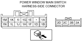
POWER WINDOW MAIN SWITCH INSPECTION
id091200002100
Auto-open/close Function (Front Door Type)
1. Disconnect the negative battery cable.
2. Remove the inner garnish. (driver-side) (See INNER GARNISH REMOVAL/INSTALLATION.)
3. Remove the front door trim. (driver-side) (See FRONT DOOR TRIM REMOVAL/INSTALLATION.)
4. Connect the power window main switch connector.
5. Connect the negative battery cable.
6. Measure the voltage at each terminal.
7. If the system does not work properly even though the inspection items or related wiring harnesses do not have any malfunction, replace the power window main switch. (See POWER WINDOW MAIN SWITCH REMOVAL/INSTALLATION.)
Terminal voltage table (reference)
ac9wzw00001642
|
|
Terminal |
Signal name |
Connected to |
Measured condition |
Voltage (V)/Continuity |
Inspection item (s) |
|---|---|---|---|---|---|
|
1A
|
Open signal
|
Power window motor (LR)
|
While door glass is opening
|
B+
|
• Power window motor (LR)
• Related wiring harnesses
|
|
While door glass is closing
|
1.0 or less
|
||||
|
1B
|
Power supply
|
P.WIND 30 A fuse
|
Under any condition
|
B+
|
• P.WIND 30 A fuse
• Related wiring harnesses
|
|
1D
|
Close signal
|
Power window motor (LR)
|
While door glass is opening
|
1.0 or less
|
• Power window motor (LR)
• Related wiring harnesses
|
|
While door glass is closing
|
B+
|
||||
|
1E
|
IG 1
|
METER 10 A fuse
|
Switch the ignition ON
|
B+
|
• METER 10 A fuse
• Related wiring harnesses
|
|
Switch the ignition OFF (LOCK)
|
1.0 or less
|
||||
|
1F
|
Power-cut signal
|
Power window subswitch
|
Switch the ignition ON and power-cut switch at UNLOCK
|
B+
|
• Power window subswitch
• Related wiring harnesses
|
|
1G
|
Communication
|
Power window subswitch
|
Because this terminal is for communication, good/no good judgment by terminal voltage is not possible.
|
• Power window subswitch
• Related wiring harnesses
|
|
|
1H
|
Door open/close signal
|
BCM
|
Any door is open
|
1.0 or less
|
• BCM
• Related wiring harnesses
|
|
All door is close
|
B+
|
||||
|
1I
|
Close signal
|
Power window motor (driver-side)
|
While door glass is opening
|
1.0 or less
|
• Power window motor (driver-side)
• Related wiring harnesses
|
|
While door glass is closing
|
B+
|
||||
|
1J
|
Open signal
|
Power window motor (RR)
|
While door glass is opening
|
B+
|
• Power window motor (RR)
• Related wiring harnesses
|
|
While door glass is closing
|
1.0 or less
|
||||
|
1K
|
Open signal
|
Power window motor (driver-side)
|
While door glass is opening
|
B+
|
• Power window motor (driver-side)
• Related wiring harnesses
|
|
While door glass is closing
|
1.0 or less
|
||||
|
1L
|
Close signal
|
Power window motor (RR)
|
While door glass is opening
|
1.0 or less
|
• Power window motor (RR)
• Related wiring harnesses
|
|
While door glass is closing
|
B+
|
||||
|
1M
|
GND
|
Body ground
|
Under any condition
|
1.0 or less
|
• Related wiring harnesses
|
|
1N
|
Power supply
|
P.WIND 30 A fuse
|
Under any condition
|
B+
|
• P.WIND 30 A fuse
• Related wiring harnesses
|
|
2A
|
Sensor ground
|
Power window motor (driver-side)
|
Under any condition
|
1.0 or less
|
• Power window motor (driver-side)
• Related wiring harnesses
|
|
2B
|
Power supply
|
Power window motor (driver-side)
|
While IG ON or IG OFF timer works
|
B+
|
• Power window motor (driver-side)
• Related wiring harnesses
|
|
2C
|
Pulse 1
|
Power window motor (driver-side)
|
Door glass is not in motion
|
0 or 5.0
|
• Power window motor (driver-side)
• Related wiring harnesses
|
|
Door glass is in motion
|
Alternates between 0 and 5.0
|
||||
|
2D
|
Pulse 2
|
Power window motor (driver-side)
|
Door glass is in motion
|
Alternates between 0 and 5.0
|
• Power window motor (driver-side)
• Related wiring harnesses
|
|
Door glass is not in motion
|
0 or 5.0
|
||||
Auto-open/close Function (All Door Type)
1. Disconnect the negative battery cable.
2. Remove the inner garnish. (driver-side) (See INNER GARNISH REMOVAL/INSTALLATION.)
3. Remove the front door trim. (driver-side) (See FRONT DOOR TRIM REMOVAL/INSTALLATION.)
4. Connect the power window main switch connector.
5. Connect the negative battery cable.
6. Measure the voltage at each terminal.
7. If the system does not work properly even though the inspection items or related wiring harnesses do not have any malfunction, replace the power window main switch. (See POWER WINDOW MAIN SWITCH REMOVAL/INSTALLATION.)
Terminal voltage table (reference)
ac9wzw00001767
|
|
Terminal |
Signal name |
Connected to |
Measured condition |
Voltage (V)/Continuity |
Inspection item (s) |
|---|---|---|---|---|---|
|
A
|
GND
|
Body ground
|
Under any condition
|
1.0 or less
|
• Related wiring harnesses
|
|
B
|
Close signal
|
Power window motor (driver-side)
|
While door glass is opening
|
1.0 or less
|
• Power window motor (driver-side)
• Related wiring harnesses
|
|
While door glass is closing
|
B+
|
||||
|
D
|
Sensor ground
|
Power window motor (driver-side)
|
Under any condition
|
1.0 or less
|
• Power window motor (driver-side)
• Related wiring harnesses
|
|
E
|
Power supply
|
Power window motor (driver-side)
|
While IG ON or IG OFF timer works
|
B+
|
• Power window motor (driver-side)
• Related wiring harnesses
|
|
F
|
IG 1
|
METER 10 A fuse
|
Switch the ignition ON
|
B+
|
• METER 10 A fuse
• Related wiring harnesses
|
|
Switch the ignition OFF (LOCK)
|
1.0 or less
|
||||
|
H
|
Pulse 1
|
Power window motor (driver-side)
|
Door glass is not in motion
|
0 or 5.0
|
• Power window motor (driver-side)
• Related wiring harnesses
|
|
Door glass is in motion
|
Alternates between 0 and 5.0
|
||||
|
I
|
Communication
|
Power window subswitch
|
Because this terminal is for communication, good/no good judgment by terminal voltage is not possible.
|
• Power window subswitch
• Related wiring harnesses
|
|
|
J
|
Pulse 2
|
Power window motor (driver-side)
|
Door glass is in motion
|
Alternates between 0 and 5.0
|
• Power window motor (driver-side)
• Related wiring harnesses
|
|
Door glass is not in motion
|
0 or 5.0
|
||||
|
K
|
Door open/close signal
|
BCM
|
Any door is open
|
1.0 or less
|
• BCM
• Related wiring harnesses
|
|
All door is close
|
B+
|
||||
|
L
|
Power-cut signal
|
Power window subswitch
|
Switch the ignition ON and power-cut switch at UNLOCK
|
B+
|
• Power window subswitch
• Related wiring harnesses
|
|
M
|
Power supply
|
P.WIND 30 A fuse
|
Under any condition
|
B+
|
• P.WIND 30 A fuse
• Related wiring harnesses
|
|
N
|
Open signal
|
Power window motor (driver-side)
|
While door glass is opening
|
B+
|
• Power window motor (driver-side)
• Related wiring harnesses
|
|
While door glass is closing
|
1.0 or less
|
||||
