|
ac9wzw00001658
POWER OUTER MIRROR INSPECTION
id091200002700
Mirror Glass Adjustment
1. Disconnect the negative battery cable.
2. Remove the inner garnish. (See INNER GARNISH REMOVAL/INSTALLATION.)
3. Disconnect the power outer mirror connector.
4. Remove the front door trim. (See FRONT DOOR TRIM REMOVAL/INSTALLATION.)
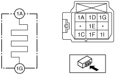
5. Apply battery positive voltage and connect the ground to the power outer mirror terminals and inspect the power outer mirror operation.
ac9wzw00001658
|
|
Mirror operation direction |
Terminal |
|
|---|---|---|
|
B+ |
Ground |
|
|
Up
|
1C
|
1F
|
|
Down
|
1F
|
1C
|
|
Left
|
1I
|
1F
|
|
Right
|
1F
|
1I
|
With Heated Mirror
1. Disconnect the negative battery cable.
2. Remove the inner garnish. (See INNER GARNISH REMOVAL/INSTALLATION.)
3. Disconnect the power outer mirror connector.
4. Remove the front door trim. (See FRONT DOOR TRIM REMOVAL/INSTALLATION.)
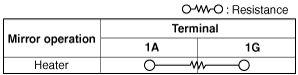
5. Apply battery voltage to power outer mirror connector terminal 1A, and connect terminal 1G to ground.
ac9wzw00001659
|
ac9wzw00001660
|
With Position Memory
1. Disconnect the negative battery cable.
2. Remove the inner garnish. (See INNER GARNISH REMOVAL/INSTALLATION.)
3. Disconnect the power outer mirror connector.
4. Remove the front door trim. (See FRONT DOOR TRIM REMOVAL/INSTALLATION.)
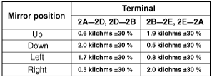
5. Verify that the continuity is as indicated in the table.
ac9wzw00000835
|
ac9wzw00000836
|