ON-BOARD DIAGNOSTIC SYSTEM FUNCTION [Bluetooth SYSTEM (HANDS-FREE TELEPHONE (HF/TEL) SYSTEM)]
id0920001018a9
Self-diagnostic Function
Malfunction detection function
-
• The malfunction detection function detects malfunctions occurring in the Bluetooth system (hands-free telephone (HF/TEL) system).
Memory function
-
• The memory function converts a malfunction detected by the malfunction detection function to a DTC and stores it. The error currently occurring is stored as a present malfunction. Up to six DTCs can be stored as a past malfunction. The DTCs, together with the number of times the ignition switch has been turned off after the occurrence of an error (maximum of 255 times), are stored as a past malfunction.
Display function
-
• To display DTCs on the display that have been recorded in the memory function, activate the on-board diagnostic function by operating the audio unit/car-navigation unit. Refer to the Workshop Manual for the activation procedure of the on-board diagnostic function.
-
• The DTC consists of the following codes and numbers:
Error history display screen
-
― Current malfunction
― Number of times the ignition switch has been turned off after the occurrence of an error
― Detail Switch
Detail display screen
-
― Error code
― Check content
― Number of times present/past malfunction has occurred
DTC table
|
DTC
|
Description
|
|
Device code
|
Error code
|
|
26
|
81
|
CAN system communication error
|
|
26
|
82
|
Microphone circuit malfunction
|
|
26
|
83
|
Microphone circuit malfunction
|
|
26
|
84
|
Microphone circuit malfunction
|
|
26
|
85
|
Steering switch circuit malfunction
|
|
26
|
86
|
Bluetooth unit internal malfunction
|
|
—
|
—
|
DTC is not recorded.
|
Diagnostic Assist Function
• The connection condition and specification of the Bluetooth system (hands-free telephone (HF/TEL) system) related parts can be verified by displaying them in the LCD display. The password for the Bluetooth system (hands-free telephone (HF/TEL) system), which is set by the user, can also be reset. Refer to the Workshop Manual for the diagnostic assist function activation procedure.
• Input a diagnostic assist code and display the unit’s operation conditions, or force the operation to examine the integrity of functions (parts).
• For start-up methods of each mode, refer to the Workshop Manual.
Diagnostic assist code table
|
No.
|
Content/function
|
|
37
|
Connection condition verification
|
|
38
|
Software version verification
|
|
39
|
Password reset
|
 ac9wzn00000645― Current malfunction― Number of times the ignition switch has been turned off after the occurrence of an error― Detail Switch
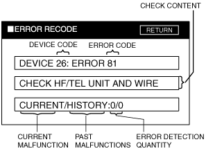 ac9wzn00000646― Error code― Check content― Number of times present/past malfunction has occurred