|
bawuua00000204
TRANSFER ASSEMBLY (VEHICLES WITH TRANSFER OIL COOLER)
id031600511200
Before Service Precautions
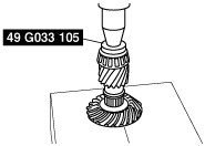
Drive Gear Case Component Assembly
bawuua00000204
|
|
1
|
Drive gear
|
|
2
|
Bearing (LH)
|
|
3
|
Bearing (RH)
|
|
4
|
Bearing outer race (RH)
|
|
5
|
Bearing outer race (LH)
|
|
6
|
Oil seal (RH inner)
|
|
7
|
Drive gear component
|
|
8
|
Spacer
|
|
9
|
Adjustment shim
|
|
10
|
Bearing cap
|
|
11
|
Oil seal (RH outer)
|
|
12
|
Oil seal (LH inner)
|
|
13
|
Oil seal (LH outer)
|
|
14
|
Drive gear shaft
|
|
15
|
Baffle plate
|
|
16
|
Drive gear case
|
Drive Gear Case Component Assembly Procedure
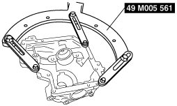
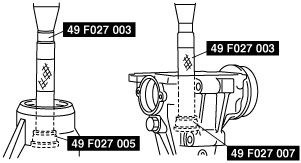
1. Install the drive gear case to the SST.
bawuua00000205
|
2. Install the baffle plate.
bawuua00000206
|
3. Using a press, assemble the bearing (RH).
bawuua00000207
|
4. Using a press, assemble the bearing (LH).
bawuua00000208
|
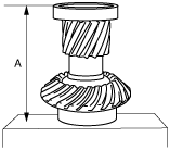
5. Temporarily assemble the bearing outer race (RH) and spacer to the drive gear.
6. Place the drive gear component on the surface plate as shown in the figure, and measure the height using a vernier caliper or height gauge. This is dimension A.
bawuua00000209
|
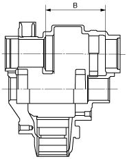
7. Measure the width of the drive gear installation area in the drive gear case. This is dimension B.
bawuua00000210
|
8. The maximum and minimum thickness C of the adjustment shim can be expressed by the following formula:
9. If the thickness of the installed adjustment shim is within the C range, use the shim as it is.
10. If the thickness of the installed adjustment shim is not within the C range, select the appropriate adjustment shim from the table below and use it.
Adjustment shim
|
Identification mark |
Thickness (mm {in}) |
Identification mark |
Thickness (mm {in}) |
|---|---|---|---|
|
350
|
3.50 {0.1378}
|
420
|
4.20 {0.1654}
|
|
355
|
3.55 {0.1398}
|
425
|
4.25 {0.1673}
|
|
360
|
3.60 {0.1417}
|
430
|
4.30 {0.1693}
|
|
365
|
3.65 {0.1437}
|
435
|
4.35 {0.1713}
|
|
370
|
3.70 {0.1457}
|
440
|
4.40 {0.1732}
|
|
375
|
3.75 {0.1476}
|
445
|
4.45 {0. 1752}
|
|
380
|
3.80 {0.1496}
|
450
|
4.50 {0.1772}
|
|
385
|
3.85 {0.1516}
|
455
|
4.55 {0.1791}
|
|
390
|
3.90 {0.1535}
|
460
|
4.60 {0. 1811}
|
|
395
|
3.95 {0.1555}
|
–
|
–
|
|
400
|
4.00 {0.1575}
|
–
|
–
|
|
405
|
4.05 {0.1594}
|
–
|
–
|
|
410
|
4.10 {0.1614}
|
–
|
–
|
|
415
|
4.15 {0.1634}
|
–
|
–
|
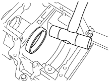
11. Using the plastic hammer, install the bearing outer race (LH).
bawuua00000211
|
12. Install the drive gear component.
bawuua00000212
|
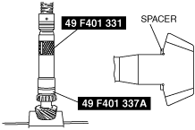
13. Install the spacer with its notch facing the bearing, and also facing upward, as shown in the figure.
bawuua00000213
|
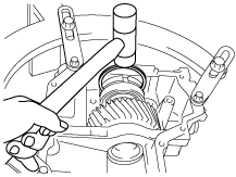
14. Using a plastic hammer, assemble the adjustment shim.
bawuua00000214
|
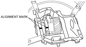
15. Align the bearing cap alignment marks, assemble the bearing cap.
bawuua00000215
|
16. Assemble the SST to the drive gear shaft, and hand-tighten the nut.
bawuua00000216
|
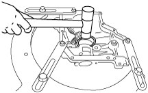
17. Install the drive gear shaft with the SST assembled and verify that the preload is within the specification using the torque wrench as shown in the figure.
bawuua00000217
|
18. Remove the drive gear shaft.
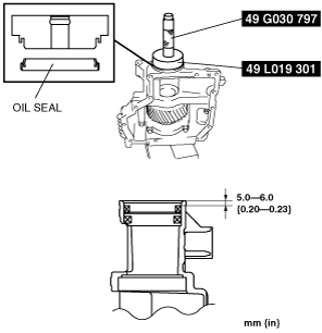
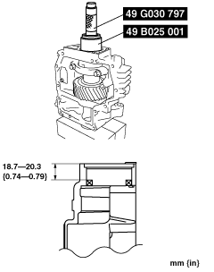
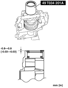
19. Using a SSTs, install the oil seals.
LH inner
bawuua00000218
|
LH outer
bawuua00000219
|
RH inner
bawuua00000220
|
RH outer
bawuua00000221
|
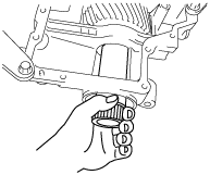
20. Install the C-ring to the drive gear shaft and insert the drive gear shaft until it is secured by the C-ring.
bawuua00000222
|
21. Pull the drive gear shaft by hand and verify that the drive gear shaft is secured by the C-ring at the specified position.
bawuua00000223
|
Front Carrier Component Assembly
bawwza00000009
|
|
1
|
Bearing outer race (rear)
|
|
2
|
Bearing outer race (front)
|
|
3
|
Spacer
|
|
4
|
Bearing (front)
|
|
5
|
Distance piece
|
|
6
|
Bearing (rear)
|
|
7
|
Drive pinion gear
|
|
8
|
Oil seal
|
|
9
|
Companion flange
|
|
10
|
Washer
|
|
11
|
Locknut
|
|
12
|
Ring gear shaft
|
|
13
|
Ring gear
|
|
14
|
Bearing (side)
|
|
15
|
Bearing outer race (side)
|
|
16
|
Adjustment shim
|
|
17
|
Spacer
|
|
18
|
Ring gear component
|
|
19
|
Tubular pin
|
|
20
|
Bearing cap
|
|
21
|
Oil pump shaft
|
|
22
|
Oil pump
|
|
23
|
Ring gear lockbolt
|
|
24
|
Side cover
|
|
25
|
Oil strainer
|
|
26
|
Oil pipe
|
Front Carrier Component Assembly Procedure
1. Using a press, assemble the opposite ring gear side bearing (side) to the ring gear shaft.
bawuua00000225
|
2. Using a press, assemble the ring gear to the ring gear shaft
bawuua00000226
|
3. Using a press, assemble the ring gear side bearing (side).
bawuua00000227
|
4. Temporarily assemble the bearing outer races (side).
5. Place the ring gear component on the surface plate as shown in the figure, and measure the height using a vernier caliper or height gauge. This is dimension A.
bawuua00000228
|
6. Measure the width of the front carrier ring gear installation area with the spacer installed. This is dimension B.
bawuua00000229
|
7. The maximum and minimum total thickness C of the adjustment shims on both sides can be expressed by the following formula:
8. If the total thickness of the installed adjustment shims is within the C range, use the shims as they are.
9. If the total thickness of the installed adjustment shims is not within the C range, select the appropriate number of adjustment shims from the table below and use them.
Adjustment shim
|
Identification mark |
Thickness (mm {in}) |
Identification mark |
Thickness (mm {in}) |
|---|---|---|---|
|
350
|
3.50 {0.1378}
|
410
|
4.10 {0.1614}
|
|
355
|
3.55 {0.1398}
|
415
|
4.15 {0.1634}
|
|
360
|
3.60 {0.1417}
|
420
|
4.20 {0.1654}
|
|
365
|
3.65 {0.1437}
|
425
|
4.25 {0.1673}
|
|
370
|
3.70 {0.1457}
|
430
|
4.30 {0.1693}
|
|
375
|
3.75 {0.1476}
|
435
|
4.35 {0.1713}
|
|
380
|
3.80 {0.1496}
|
440
|
4.40 {0.1732}
|
|
385
|
3.85 {0.1516}
|
445
|
4.45 {0.1752}
|
|
390
|
3.90 {0.1535}
|
450
|
4.50 {0.1772}
|
|
395
|
3.95 {0.1555}
|
455
|
4.55 {0.1791}
|
|
400
|
4.00 {0.1574}
|
460
|
4.60 {0.1811}
|
|
405
|
4.05 {0.1594}
|
–
|
–
|
10. Install the front carrier to the SST.
bawuua00000230
|
11. Install the adjustment shim chosen for the front carrier ring gear side and spacer on opposite side.
12. Assemble the ring gear component to the front carrier.
13. Using the plastic hammer, assemble the selected adjustment shim in between the spacer and bearing race as shown in the figure.
bawuua00000231
|
14. After installing the tubular pins, align the alignment marks of the bearing caps, assemble the bearing caps, and tighten the bolts temporarily.
bawuua00000232
|
15. Install the ring gear lockbolt and inspect the ring gear bearing preload.
16. Follow the disassembling procedure in Step 11 to remove the ring gear component.
17. Using the SSTs, assemble the bearing outer races.
bawuua00000233
|
18. Using the SSTs, adjust the drive pinion height as follows:
bawuua00000234
|
bawuua00000235
|
bawuua00000236
|
Spacer
|
Identification mark |
Thickness (mm {in}) |
Identification mark |
Thickness (mm {in}) |
|---|---|---|---|
|
08
|
3.08 {0.1213}
|
29
|
3.29 {0.1295}
|
|
09
|
3.095 {0.1219}
|
30
|
3.305 {0.1301}
|
|
11
|
3.11 {0.1224}
|
32
|
3.32 {0.1307}
|
|
12
|
3.125 {0.1230}
|
33
|
3.335 {0.1313}
|
|
14
|
3.14 {0.1236}
|
35
|
3.35 {0.1319}
|
|
15
|
3.155 {0.1242}
|
36
|
3.365 {0.1325}
|
|
17
|
3.17 {0.1248}
|
38
|
3.38 {0.1331}
|
|
18
|
3.185 {0.1254}
|
39
|
3.395 {0.1335}
|
|
20
|
3.20 {0.1260}
|
41
|
3.41 {0.1343}
|
|
21
|
3.215 {0.1266}
|
42
|
3.425 {0.1348}
|
|
23
|
3.23 {0.1272}
|
44
|
3.44 {0.1354}
|
|
24
|
3.245 {0.1278}
|
45
|
3.455 {0.1360}
|
|
26
|
3.26 {0.1283}
|
47
|
3.47 {0.1366}
|
|
27
|
3.275 {0.1289}
|
–
|
–
|
19. Assemble the spacer selected for pinion height adjustment with the rounded off side facing the gears.
20. Using the SST, assemble the bearing (front) to the drive pinion gear.
bawuua00000237
|
21. Assemble a new distance piece to the drive pinion gear.
22. Assemble the drive pinion gear to the front carrier.
23. Install the bearing (rear), companion flange, washer, and new locknut to the drive pinion and temporarily tighten.
24. Rotate the companion flange by hand and seat the bearing.
25. Using the SST, tighten the locknut from the lower limit of the specified tightening torque and set to the preload value. Note the tightening torque when the specified preload value is obtained.
bawuua00000546
|
26. Remove the locknut, washer, and companion flange.
27. Apply oil to the lip area of a new oil seal.
28. Using the SST, assemble the oil seal.
bawuua00000538
|
29. Apply the grease to the bearing contact surface of the companion flange.
30. Assemble the companion flange.
31. Using the SST, tighten the new locknut to the tightening torque noted when the preload was adjusted.
bawuua00000546
|
32. Reverify the preload.
33. Assemble the ring gear component following the procedure in Step 11 to 14.
34. Set the dial gauge with the measuring probe attached perpendicularly to the end of one of the ring gear teeth.
35. Secure the drive pinion and measure the backlash from when the ring gear is moved.
bawuua00000539
|
36. If the backlash is not within the specified range above, adjust it by sliding the ring gear in the shaft direction.
37. Tighten the bearing cap bolts.
38. Perform the drive pinion and ring gear tooth contact inspection.
bawuua00000540
|
bawuua00000242
|
bawuua00000243
|
39. Using a suitable wrench, secure the ring gear shaft and tighten the new ring gear lockbolt to the specified tightening torque.
bawuua00000244
|
40. Align the cast hexagon of the oil pump shaft and assemble the oil pump and oil pump shaft.
41. Align the oil holes of the oil pump and front carrier.
bawuua00000245
|
42. Assemble the oil strainer.
43. Assemble the oil pipe.
44. Apply oil to a new O-ring and assemble the side cover.
45. Assemble the side cover to the front carrier.
46. Remove the front carrier component from the SST.
Transfer Component Assembly
bawuua00000246
|
|
1
|
Front carrier component
|
|
2
|
Drive gear case component
|
|
3
|
Oil cooler
|
|
4
|
Drain plug
|
|
5
|
Oil level plug
|
Transfer Component Assembly Procedure
1. Clean the alignment surface of the front carrier and drive gear case, and lightly apply silicone sealant.
2. Assemble the transfer component.
3. Install the oil cooler.
4. Tighten the oil cooler installation bolt with a O-ring.
5. Tighten the drain plug with a new washer.