FUEL PUMP UNIT INSPECTION [MZI-3.7]


id0114d2801100

Caution
•  It is normal to hear the fuel pump operating when the ignition switch is turned to the ON position.
Note
•  To improve start ability, the fuel pump control operates the fuel pump unit when the ignition switch is turned to the ON position. Due to this, fuel pressure is rapidly increased and fuel control is stabilized.

Operation Test

1.  Follow “BEFORE SERVICE PRECAUTION” before performing any work operations to prevent fuel from spilling from the fuel system. (See BEFORE SERVICE PRECAUTION [MZI-3.7].)

2.  Remove the fuel-filler cap. (See FUEL TANK REMOVAL/INSTALLATION [MZI-3.7].)

3.  Start the fuel pump using the following procedure:


Using M-MDS

1.  Connect the M-MDS to the DLC-2.

ac9uuw00000116

2.  Turn the ignition switch to the ON position.

3.  Using the simulation function FP, verify that operation sound is heard from the fuel pump when FP is turned from OFF to ON.

•  If the operation sound cannot be verified, measure the voltage at fuel pump wiring harness-side connector terminal B.
ac9uuw00001003
―  If as specified, inspect the following:
•  Fuel pump continuity
―  If not within the specification, inspect the following:
•  Fuel pump relay
•  Wiring harnesses and connectors between battery—fuel pump relay—fuel pump
Standard
B+ (Ignition switch at ON)


Without using M-MDS

1.  Disconnect the negative battery cable. (See BATTERY REMOVAL/INSTALLATION [MZI-3.7].)

2.  Remove the fuel pump relay.

Caution
•  Short the specified terminals because shorting the wrong terminal of the main fuse block may cause malfunctions.

3.  Using a jumper wire, short fuel pump relay terminals C and D in the main fuse block.

ac9uuw00001018

4.  Connect the negative battery cable and operate the fuel pump.

5.  Verify that operation sound is heard from the fuel pump when ignition switch turn to the ON position.

•  If the operation sound cannot be verified, measure the voltage at fuel pump wiring harness-side connector terminal B.
ac9uuw00001003
―  If as specified, inspect the following:
•  Fuel pump continuity
―  If not within the specification, inspect the following:
•  Fuel pump relay
•  Wiring harnesses and connectors between battery—fuel pump relay—fuel pump
Standard
B+ (Ignition switch at ON)

6.  Disconnect the jumper wire.

4.  Complete the “AFTER SERVICE PRECAUTION”. (See AFTER SERVICE PRECAUTION [MZI-3.7].)


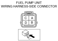
Continuity Inspection

1.  Disconnect the negative battery cable. (See BATTERY REMOVAL/INSTALLATION [MZI-3.7].)

2.  To remove the service hole cover, remove the following parts:

(1)  Second-row seat (See SECOND-ROW SEAT REMOVAL/INSTALLATION.)
(2)  Edge cover (See LONG SLIDER REMOVAL/INSTALLATION.)
(3)  Long slider cover (See LONG SLIDER REMOVAL/INSTALLATION.)
(4)  Rear heat duct No.3 (See REAR HEAT DUCT COMPONENT REMOVAL/INSTALLATION.)
(5)  Service hole cover (See FUEL PUMP UNIT REMOVAL/INSTALLATION [MZI-3.7].)

3.  Disconnect the fuel pump unit connector.

4.  Inspect for continuity between fuel pump unit connector terminals B and D.

ac9uuw00001003

•  If there is no continuity, replace the fuel pump unit. (See FUEL PUMP UNIT REMOVAL/INSTALLATION [MZI-3.7].)