 |
ac9uun00000488
DSC/RSC HU PART CONSTRUCTION/OPERATION
id041800818200
Construction
Function of main component parts
|
Part name |
Function |
|---|---|
|
Inlet solenoid valve
|
• Adjusts the fluid pressure in each brake system according to DSC/RSC HU/CM signals.
|
|
Outlet solenoid valve
|
• Adjusts the fluid pressure in each brake system according to DSC/RSC HU/CM signals.
|
|
Stability control solenoid valve
|
• Switches the brake hydraulic circuits during and according to normal braking, ABS and EBD control, TCS control and DSC control, RSC control.
|
|
Traction control solenoid valve
|
• Switches the brake hydraulic circuits during and according to normal braking, ABS and EBD control, TCS control and DSC control, RSC control.
|
|
Reservoir
|
• Temporarily stores brake fluid from the caliper piston to ensure smooth pressure reduction during ABS and EBD control, TCS control and DSC control, RSC control.
|
|
Pump
|
• Returns the brake fluid stored in the reservoir to the master cylinder during ABS and DSC control, RSC control.
• Increases brake fluid pressure and sends brake fluid to each caliper piston during TCS control and DSC control, RSC control.
|
|
Pump motor
|
• Operates the pump according to DSC/RSC HU/CM signals.
|
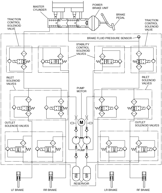
Hydraulic circuit diagram
ac9uun00000488
|
Operation
During normal braking
Solenoid valve operation table
|
Traction control solenoid valve |
Stability control solenoid valve |
Inlet solenoid valve |
Outlet solenoid valve |
Pump motor, pump |
||||||||
|---|---|---|---|---|---|---|---|---|---|---|---|---|
|
LF—RR |
RF—LR |
LF—RR |
RF—LR |
LF |
RF |
LR |
RR |
LF |
RF |
LR |
RR |
|
|
OFF (open)
|
OFF (closed)
|
OFF (open)
|
OFF (closed)
|
Stopped
|
||||||||
Hydraulic circuit diagram
ac9uun00000489
|
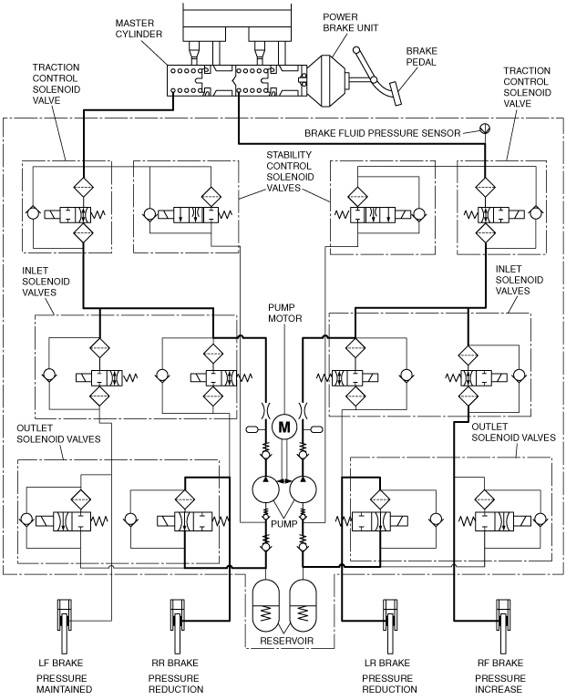
During ABS and EBD control
Solenoid valve operation table
|
|
Traction control solenoid valve |
Stability control solenoid valve |
Inlet solenoid valve |
Outlet solenoid valve |
Pump motor, pump |
||||||||
|---|---|---|---|---|---|---|---|---|---|---|---|---|---|
|
LF—RR |
RF—LR |
LF—RR |
RF—LR |
LF |
RF |
LR |
RR |
LF |
RF |
LR |
RR |
||
|
During Pressure increase mode
|
OFF (open)
|
OFF (closed)
|
OFF (open)
|
OFF (closed)
|
Stopped
|
||||||||
|
During pressure maintain mode
|
OFF (open)
|
OFF (closed)
|
ON (closed)
|
OFF (closed)
|
Stopped
|
||||||||
|
During pressure reduction mode
|
OFF (open)
|
OFF (closed)
|
ON (closed)
|
ON (open)
|
Operating
|
||||||||
Hydraulic circuit diagram
ac9uun00000490
|
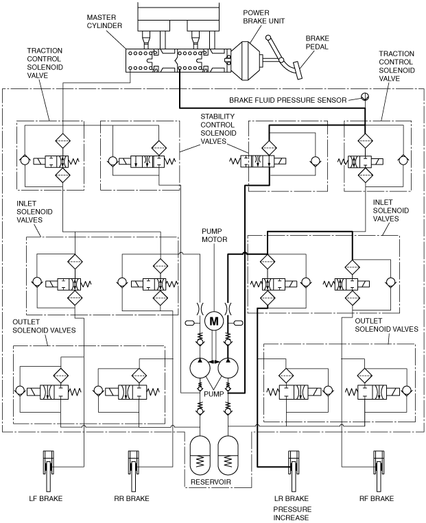
During DSC control (suppress oversteer tendency) and TCS control
Solenoid valve operation table
|
|
Traction control solenoid valve |
Stability control solenoid valve |
Inlet solenoid valve |
Outlet solenoid valve |
Pump motor, pump |
||||||||
|---|---|---|---|---|---|---|---|---|---|---|---|---|---|
|
LF—RR |
RF—LR |
LF—RR |
RF—LR |
LF |
RF |
LR |
RR |
LF |
RF |
LR |
RR |
||
|
During pressure increase mode
|
ON
(closed)
|
OFF
(closed)
|
ON
(open)
|
ON
(closed)
|
OFF
(open)
|
ON
(closed)
|
OFF
(open)
|
OFF (closed)
|
Operating
|
||||
|
During pressure maintain mode
|
OFF
(open)
|
ON
(closed)
|
OFF (closed)
|
OFF
(open)
|
ON (closed)
|
ON (closed)
|
OFF
(open)
|
OFF (closed)
|
Operating
|
||||
|
During pressure reduction mode
|
OFF
(open)
|
ON
(closed)
|
OFF (closed)
|
OFF
(open)
|
ON (closed)
|
OFF
(open)
|
OFF
(closed)
|
ON
(open)
|
OFF
(closed)
|
OFF
(closed)
|
Operating
|
||
Hydraulic circuit diagram
ac9uun00000491
|
During DSC control (to suppress understeer tendency)
Solenoid valve operation table
|
|
Traction control solenoid valve |
Stability control solenoid valve |
Inlet solenoid valve |
Outlet solenoid valve |
Pump motor, pump |
||||||||
|---|---|---|---|---|---|---|---|---|---|---|---|---|---|
|
LF—RR |
RF—LR |
LF—RR |
RF—LR |
LF |
RF |
LR |
RR |
LF |
RF |
LR |
RR |
||
|
During pressure increase mode
|
ON (closed)
|
OFF
(closed)
|
ON
(open)
|
OFF
(open)
|
ON
(closed)
|
OFF
(open)
|
OFF (closed)
|
Operating
|
|||||
|
During pressure maintain mode
|
OFF
(open)
|
ON
(closed)
|
OFF (closed)
|
OFF
(open)
|
ON (closed)
|
OFF
(open)
|
OFF (closed)
|
Operating
|
|||||
|
During pressure reduction mode
|
OFF
(open)
|
ON
(closed)
|
OFF (closed)
|
OFF
(open)
|
ON (closed)
|
OFF
(open)
|
OFF
(closed)
|
ON
(open)
|
OFF
(closed)
|
Operating
|
|||
Hydraulic circuit diagram
ac9uun00000492
|