 |
ac9uun00000441
MANUAL MODE SHIFT CONTROL OPERATION [AW6AX-EL]
id0517j6102800
Manual Mode Shift
|
Condition |
Shift control |
Note |
|---|---|---|
|
2GR→3GR up-shift command at low speed
|
• To reduce load on the ATX, upshifting is inhibited until vehicle reaches speed possible for upshifting
|
• Selector indicator “M” light and gear position indicator light flash to alert driver
|
|
3GR→4GR up-shift command at low speed
|
||
|
4GR→5GR up-shift command at low speed
|
||
|
5GR→6GR up-shift command at low speed
|
||
|
6GR→5GR down-shift command, above set speed
|
• To prevent engine over-rev, downshifting is inhibited until vehicle reaches speed possible for downshifting
|
• Gear position indicator light flash to alert driver
|
|
5GR→4GR down-shift command, above set speed
|
||
|
4GR→3GR down-shift command, above set speed
|
||
|
3GR→2GR down-shift command, above set speed
|
||
|
2GR→1GR down-shift command, above set speed
|
||
|
In 6GR deceleration, speed goes below coast-down set speed (deceleration down-shift)
|
• To assure drive stability, automatically downshifts from 6GR to 5GR
|
–
|
|
In 5GR deceleration, speed goes below coast-down set speed (deceleration down-shift)
|
• To assure drive stability, automatically downshifts from 5GR to 4GR
|
|
|
In 4GR deceleration, speed goes below coast-down set speed (deceleration down-shift)
|
• To assure drive stability, automatically downshifts from 4GR to 3GR
|
|
|
In 3GR deceleration, speed goes below coast-down set speed (deceleration down-shift)
|
• To assure drive stability, automatically downshifts from 3GR to 1GR
|
|
|
In 2GR deceleration, speed goes below coast-down set speed (deceleration down-shift)
|
• To assure drive stability, automatically downshifts from 2GR to 1GR
|
|
|
Wide open throttle at 85—95 km/h {53—58 mph} in 5GR
|
• To improve acceleration performance, 5GR to 4GR kickdown occurs
|
–
|
|
Wide open throttle at 60—70 km/h {38—43 mph} in 4GR
|
• To improve acceleration performance, 4GR to 3GR kickdown occurs
|
|
|
Wide open throttle at 36—44 km/h {23—27 mph} in 3GR
|
• To improve acceleration performance, 3GR to 2GR kickdown occurs
|
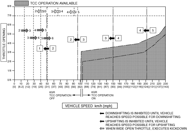
Shift Diagram
ac9uun00000441
|