 |
ac9wzw00000556
STEERING GEAR AND LINKAGE REMOVAL/INSTALLATION [L.H.D.]
id0614008009d3
1. Drain the power steering fluid. (See POWER STEERING FLUID INSPECTION.)
2. Remove the front under cover A and front under cover B. (See FRONT UNDER COVER REMOVAL/INSTALLATION.)
3. Remove the middle pipe. (See EXHAUST SYSTEM REMOVAL/INSTALLATION [MZI-3.7].)
4. Remove the transverse member. (See TRANSVERSE MEMBER REMOVAL/INSTALLATION.)
5. Remove the intermediate shaft installation bolt, and disconnect the steering shaft. (See STEERING WHEEL AND COLUMN REMOVAL/INSTALLATION.)
6. Remove the front crossmember, steering gear and linkage component. (See FRONT CROSSMEMBER REMOVAL/INSTALLATION [L.H.D.].)
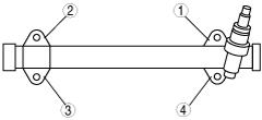
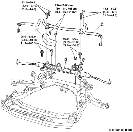
7. Remove in the order indicated in the table.
8. Install in the reverse order of removal.
9. After installation, adjust the total toe-in. (See FRONT WHEEL ALIGNMENT.)
ac9wzw00000556
|
|
1
|
Insulator
|
|
2
|
Front stabilizer
|
|
3
|
Steering gear and linkage
|
Steering Gear and Linkage Installation Note
1. Tighten the mounting bracket bolts to the specified torque in the order shown.
ac9wzw00000557
|
Bolt (Intermediate Shaft) Installation Note
1. Align the marks and install the intermediate shaft and bolt.