AIRFLOW VOLUME CONTROL OPERATION


id074000102600


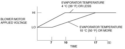
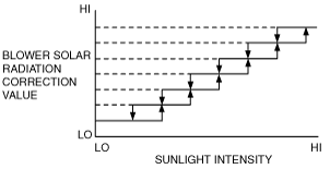
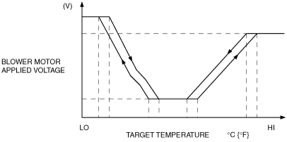
Airflow Volume Automatic Control

•  The front climate control unit calculates the applied voltage to the blower motor based on the input from the target temperature, ECT sensor and evaporator temperature sensor (front/rear), and outputs the drive signal to the power MOS FET (front/rear). However, the warm-up correction, mild start correction, MAX HOT and MAX COLD correction and defroster correction take precedence under the operation conditions of the warm-up correction, mild start correction, MAX HOT and MAX COLD correction and defroster correction.
am8rrn00000275
•  Switches the front blower motor applied voltage in 31 steps when the front power MOS FET is on. The front blower motor applied voltage is as follows:

Fan level

Front blower motor applied voltage

1
3.41 V
2
3.73 V
3
4.05 V
4
4.37 V
5
4.69 V
6
5.01 V
7
5.33 V
8
5.65 V
9
5.97 V
10
6.29 V
11
6.61 V
12
6.93 V
13
7.25 V
14
7.57 V
15
7.89 V
16
8.21 V
17
8.53 V
18
8.85 V
19
9.17 V
20
9.49 V
21
9.81 V
22
10.13 V
23
10.45 V
24
10.77 V
25
11.09 V
26
11.41 V
27
11.73 V
28
12.05 V
29
12.37 V
30
12.69 V
31 (MAX HI)
VB


Correction

Warm-up correction
•  Controls the blower motor applied voltage according to the increase in engine coolant temperature to prevent discomfort caused by a high volume of cold air blown from the vents in winter after starting the engine. However, the engine coolant temperature correction is not performed when the target temperature is low, and the airflow mode is in any mode other than VENT mode.
ac9uun00000238
Mild start correction
•  Limits blower motor applied voltage (front/rear) for 17 s after the blower motor is started in summer to prevent discomfort caused by a high volume of hot air blown from the vent. However, the mild start correction is not performed when the airflow is in any mode other than VENT or BI-LEVEL, A/C mode is OFF, or temperature of air passing through evaporator is low.
ac9uun00000239
MAX HOT and MAX COLD correction
•  When the set temperature is at 32.0, the blower motor applied voltage (front/rear) is fixed at AUTO-HI, and when the set temperature is at 15.0, the blower motor applied voltage (front/rear) is fixed at MAX-HI. However, MAX HOT correction is not performed during warm-up correction.

Correction name

Set temperature

Front blower motor applied voltage

Rear blower motor applied voltage

MAX HOT correction
32.0
AUTO-HI
AUTO-HI
MAX COLD correction
15.0
MAX-HI
MAX-HI

Defroster correction
•  To improve defrosting of the windows, a correction (+2 V) is added to the front blower motor applied voltage when the defroster switch is turned on.
Solar radiation correction
•  When the airflow mode is in VENT or BI-LEVEL, a correction is added to the airflow volume according to the amount of solar radiation.
am8rrn00000278

Airflow Volume Manual Control

•  The blower motor applied voltage (airflow volume) can be switched in seven (front) / fifteen (rear) steps with the fan switch.

Front

Fan switch

Blower motor applied voltage

1st
3.41 V
2nd
5.01 V
3rd
6.61 V
4th
8.21 V
5th
9.81 V
6th
11.41 V
7th
VB

Rear

Fan switch

Blower motor applied voltage

1st
3.41 V
2nd
3.88 V
3rd
4.35 V
4th
4.82 V
5th
5.29 V
6th
5.76 V
7th
6.23 V
8th
6.70 V
9th
7.17 V
10th
7.64 V
11th
8.11 V
12th
8.58 V
13th
9.05 V
14th
9.52 V
15th
10.0 V