DTC C1295, C1307, C1441, C1442, C1443, C1444, C144A, C144B, C144C, C144D [BCM]
id0902f5841200
DTC |
C1295 |
Steering wheel angle sensor internal fault |
---|---|---|
C1307 |
Steering wheel angle sensor encoder ring defective |
|
C1441 |
Steering phase A circuit signal is not sensed |
|
C1442 |
Steering phase B circuit signal is not sensed |
|
C1443 |
Steering phase A circuit short to ground |
|
C1444 |
Steering phase B circuit short to ground |
|
C144A |
Steering phase C circuit short to ground |
|
C144B |
Steering phase Z circuit short to ground |
|
C144C |
Steering phase C circuit signal is not sensed |
|
C144D |
Steering phase Z circuit signal is not sensed |
|
DETECTION CONDITION
|
C1295
• BCM detects steering angle sensor internal abnormality (signal overflow)
C1307
• BCM detects steering angle sensor internal abnormality (signal jump)
C1441, C1442, C144C, C144D
• Open circuit in wiring harness between BCM and steering angle sensor
C1443, C1444, C144A, C144B
• Short to GND in wiring harness between BCM and steering angle sensor
|
|
POSSIBLE CAUSE
|
• Excessive grease is adhering to solid disc for steering angle detection
• Improper installation or positioning of the steering angle sensor
• Steering wheel is off-center
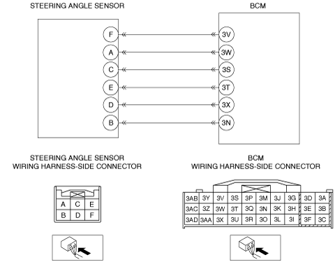
• Open circuit in wiring harness between BCM terminal 3V and steering angle sensor terminal F
• Open circuit or short to power supply in wiring harness between BCM terminal 3W and steering angle sensor terminal A
• Open circuit or short to power supply in wiring harness between BCM terminal 3S and steering angle sensor terminal C
• Open circuit or short to power supply in wiring harness between BCM terminal 3T and steering angle sensor terminal E
• Open circuit or short to power supply in wiring harness between BCM terminal 3X and steering angle sensor terminal D
• Open circuit in wiring harness between BCM terminal 3N and steering angle sensor terminal B
• Short to GND in wiring harness between BCM terminal 3V and steering angle sensor terminal F
• Short to GND in wiring harness between BCM terminal 3W and steering angle sensor terminal A
• Short to GND in wiring harness between BCM terminal 3S and steering angle sensor terminal C
• Short to GND in wiring harness between BCM terminal 3T and steering angle sensor terminal E
• Short to GND in wiring harness between BCM terminal 3X and steering angle sensor terminal D
• Steering angle sensor signal circuit short each other
• Steering angle sensor malfunction
• BCM malfunction
|
|
![]() |
Diagnostic procedure
STEP |
INSPECTION |
ACTION |
|
---|---|---|---|
1
|
INSPECT SOLID DISC FOR STEERING ANGLE DETECTION
• Visually inspect the solid disc for the steering angle detection.
• Is excessive grease adhering?
|
Yes
|
Wipe off excessive grease using a cloth, then go to Step 10.
|
No
|
Go to the next step.
|
||
2
|
INSPECT STEERING WHEEL FOR OFF-CENTER
• Drive the vehicle and inspect the steering wheel position while driving in a straight line.
• Is the steering wheel off-center?
|
Yes
|
Inspect and adjust the front wheel alignment to correct the steering wheel alignment, then go to Step 10.
(See FRONT WHEEL ALIGNMENT.)
|
No
|
Go to the next step.
|
||
3
|
INSPECT STEERING ANGLE SENSOR POWER SUPPLY CIRCUIT FOR OPEN
• Turn the ignition switch to the ON position.
• Measure the voltage between the steering angle sensor terminal F and body GND.
• Is the voltage 5 V?
|
Yes
|
Go to the next step.
|
No
|
Repair or replace the wiring harness, then go to Step 10.
|
||
4
|
INSPECT STEERING ANGLE SENSOR GND CIRCUIT FOR OPEN
• Turn the ignition switch off.
• Disconnect the steering angle sensor connector.
• Inspect for continuity between the steering angle sensor terminal B (wiring harness-side) and body GND.
• Is there continuity?
|
Yes
|
Go to the next step.
|
No
|
Repair or replace the wiring harness, then go to Step 10.
|
||
5
|
INSPECT STEERING ANGLE SENSOR SIGNAL CIRCUIT FOR OPEN
• Disconnect the BCM connector.
• Inspect for continuity between the following terminals:
• Is there continuity?
|
Yes
|
Go to the next step.
|
No
|
Repair or replace the wiring harness, then go to Step 10.
|
||
6
|
INSPECT STEERING ANGLE SENSOR SIGNAL CIRCUIT FOR SHORT TO GND
• Inspect for continuity between the following terminals and body GND:
• Is there continuity?
|
Yes
|
Repair or replace the wiring harness, then go to Step 10.
|
No
|
Go to the next step.
|
||
7
|
INSPECT STEERING ANGLE SENSOR SIGNAL CIRCUIT FOR SHORT TO POWER SUPPLY
• Measure voltage between the following and body GND:
• Is the voltage 1 V or less?
|
Yes
|
Go to the next step.
|
No
|
Repair or replace the wiring harness, then go to Step 10.
|
||
8
|
INSPECT FOR IMPROPER INSTALLATION OF STEERING ANGLE SENSOR
• Is the installation normal?
|
Yes
|
Go to the next step.
|
No
|
Repair installation or replace the steering angle sensor, then go to Step 10.
|
||
9
|
INSPECT STEERING ANGLE SENSOR
• Inspect the steering angle sensor.
• Is the steering angle sensor normal?
|
Yes
|
Go to the next step.
|
No
|
Replace the steering angle sensor, then go to Step 10.
|
||
10
|
VERIFY TROUBLESHOOTING COMPLETED
• Make sure to reconnect all disconnected connectors.
• Clear the DTC from the BCM memory using the M-MDS.
• Start the engine and drive the vehicle at 10 km/h {6.2 mph} or more.
• Is the same DTC present?
|
Yes
|
Replace the BCM.
|
No
|
DTC troubleshooting completed.
|