 |
ac9uuw00000803
FRONT SEAT DISASSEMBLY/ASSEMBLY
id091300800300
1. Disconnect the negative battery cable and wait for more than 1 minute.
2. Remove the side air bag module. (See SIDE AIR BAG MODULE REMOVAL/INSTALLATION.)
3. Disassemble in the order indicated in the table.
4. Assemble in the reverse order of disassembly.
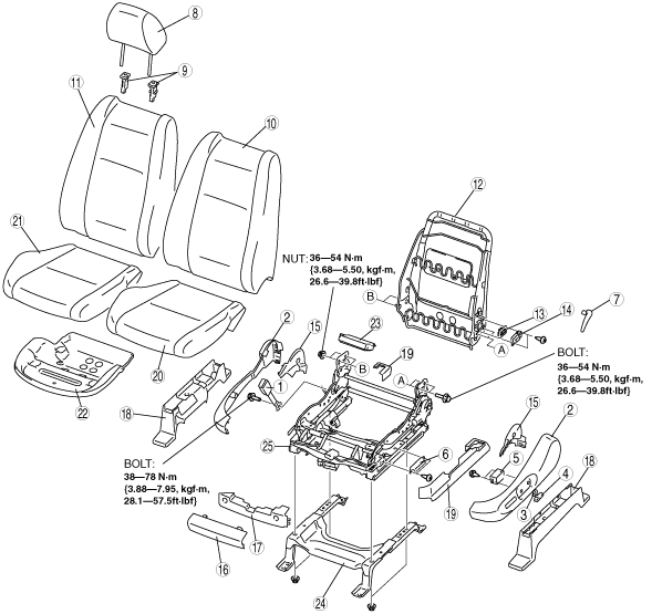
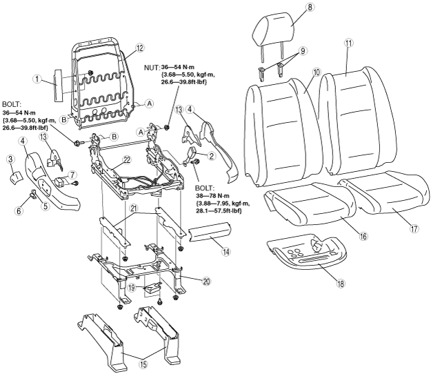
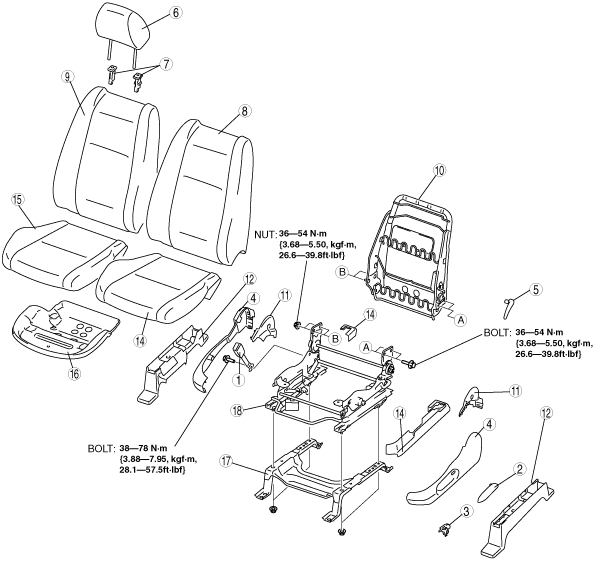
Driver Seat (Manual Seat)
ac9uuw00000803
|
|
1
|
Front buckle
|
|
2
|
Recliner lever
|
|
3
|
Lift lever
|
|
4
|
Side cover
(See Side Cover Disassembly Note.)
|
|
5
|
Lumbar support lever
|
|
6
|
Headrest
|
|
7
|
Pole guide
|
|
8
|
Seat back trim
|
|
9
|
Seat back pad
(See Side Cover Disassembly Note.)
|
|
10
|
Seat back frame
|
|
11
|
Reverse cover
|
|
12
|
Seat under bracket cover
|
|
13
|
Slide adjuster cover
|
|
14
|
Seat cushion trim
|
|
15
|
Seat cushion pad
|
|
16
|
Seat cushion frame
|
|
17
|
Seat under bracket
|
|
18
|
Slide adjuster
|
Driver Seat (Power Seat)
ac9uuw00000804
|
|
1
|
Front buckle
|
|
2
|
Side cover
(See Side Cover Disassembly Note.)
|
|
3
|
Recliner switch knob
|
|
4
|
Slider and lifter switch knob
|
|
5
|
Power seat switch
|
|
6
|
Memory switch (vehicles with position memory seat)
|
|
7
|
Lumbar support lever (vehicles without power lumber support seat)
|
|
8
|
Headrest
|
|
9
|
Pole guide
|
|
10
|
Seat back trim
|
|
11
|
Seat back pad
(See Side Cover Disassembly Note.)
|
|
12
|
Seat back frame
|
|
13
|
Lumber support switch cover (vehicles with power lumber support seat)
|
|
14
|
Lumber support switch (vehicles with power lumber support seat)
|
|
15
|
Reverse cover
|
|
16
|
Front cover No.1
|
|
17
|
Front cover No.2
|
|
18
|
Seat under bracket cover
|
|
19
|
Slide adjuster cover
|
|
20
|
Seat cushion trim
|
|
21
|
Seat cushion pad
|
|
22
|
Seat cushion frame
|
|
23
|
Position memory control module (vehicles with position memory seat)
|
|
24
|
Seat under bracket
|
|
25
|
Slide adjuster
|
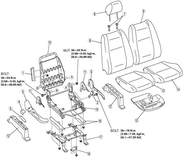
Passenger Seat (Manual Seat)
ac9uuw00000805
|
|
1
|
Side air bag module
|
|
2
|
Front buckle
|
|
3
|
Recliner lever
|
|
4
|
Anchor cover
|
|
5
|
Side cover
(See Side Cover Disassembly Note.)
|
|
6
|
Headrest
|
|
7
|
Pole guide
|
|
8
|
Seat back trim
|
|
9
|
Seat back pad
(See Side Cover Disassembly Note.)
|
|
10
|
Seat back frame
|
|
11
|
Reverse cover
|
|
12
|
Seat under bracket cover
|
|
13
|
Seat cushion trim
|
|
14
|
Seat cushion pad
|
|
15
|
Seat cushion frame
|
|
16
|
Seat weight sensor control module
|
|
17
|
Seat under bracket
|
|
18
|
Seat weight sensor
|
|
19
|
Slide adjuster
|
Passenger Seat (Power Seat)
ac9uuw00000806
|
|
1
|
Side air bag module
|
|
2
|
Front buckle
|
|
3
|
Anchor cover
|
|
4
|
Side cover
(See Side Cover Disassembly Note.)
|
|
5
|
Recliner switch knob
|
|
6
|
Slider and lifter switch knob
|
|
7
|
Power seat switch
|
|
8
|
Headrest
|
|
9
|
Pole guide
|
|
10
|
Seat back trim
|
|
11
|
Seat back pad
(See Side Cover Disassembly Note.)
|
|
12
|
Seat back frame
|
|
13
|
Reverse cover
|
|
14
|
Front cover
|
|
15
|
Seat under bracket cover
|
|
16
|
Seat cushion trim
|
|
17
|
Seat cushion pad
|
|
18
|
Seat cushion frame
|
|
19
|
Seat weight sensor control module
|
|
20
|
Seat under bracket
|
|
21
|
Seat weight sensor
|
|
22
|
Slide adjuster
|
Side Cover Disassembly Note
1. Pull the side cover outward and remove clip A.
ac9uuw00001177
|
2. Pull the side cover rearward and up at an angle, and remove tabs B and C.
Seat Back Pad Disassembly Note
1. Remove the headrest.
2. Slide hook A upward and remove it from hook B.
ac9uuw00002413
|
3. Open the fastener.
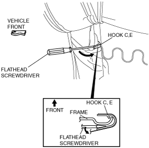
4. Insert a flathead screwdriver between hook C and the frame.
ac9uuw00002432
|
5. Pull the flathead screwdriver in the direction of the arrow as shown in the figure.
6. Remove the hook C.
7. Remove the hook D.
8. Remove the hook E.
9. Remove the hook F.
ac9uuw00002412
|
10. Remove the pole guide.
11. Remove the C ring
12. Remove the seat back trim.
13. Remove the seat back pad.
Lumber support lever disassembly note
1. Remove the pin from the lumber support lever installation part with rag.
am6uuw00000070
|
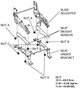
Seat Weight Sensor Installation Note
1. Install the seat weight sensor to the slide adjusters and temporarily tighten the four nuts.
ac9uuw00001161
|
2. Tighten nuts A (both right and left) at the same time to the specified tightening torque.
3. Tighten nuts B (both right and left) at the same time to the specified tightening torque.
4. Install the seat under bracket to the seat weight sensor and temporarily tighten the four nuts.
5. Tighten nuts C (both right and left) at the same time to the specified tightening torque.
6. Tighten nuts D (both right and left) at the same time to the specified tightening torque.
Power Seat Switch Wiring Harness Removal Note
1. Remove the power seat switch wiring harness from the hook A and B.
ac9wzw00001546
|
Power Seat Switch Wiring Harness Installation Note
1. After installing the side cover, install the power seat switch wiring harness to hooks A and B and the marks by the green tape on the power seat switch wiring harness shown in the figure.
ac9wzw00001547
|