 |
ac9uun00000439
ON-BOARD DIAGNOSTIC SYSTEM FUNCTION [AUDIO (STANDARD AUDIO)]
id0920001018a6
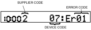
Self-diagnostic Function
Malfunction detection function
Memory function
Display function
ac9uun00000439
|
|
Supplier code |
Supplier name |
|---|---|
|
1
|
SANYO Automedia
|
|
2
|
Panasonic
|
|
3
|
Clarion
|
|
4
|
Pioneer
|
|
Device code |
Parts name |
|---|---|
|
03
|
CD player
|
|
09
|
Base unit
|
|
10
|
MP3 applicable CD player
|
|
16
|
CAN system
|
|
17
|
CAN communication line
|
|
21
|
Audio panel
|
|
22
|
MP3 applicable CD changer
|
|
23
|
Audio amplifier
|
|
Error code |
Malfunction description |
|---|---|
|
01
|
Internal mechanism error
|
|
02
|
Servo mechanism error
|
|
03
|
Mechanism stuck
|
|
04
|
Tape malfunction
|
|
07
|
Disc reading error
|
|
08
|
Blank media
|
|
10
|
BUS line (communication line) error
|
|
11
|
CAN line (communication line) error
|
|
12
|
CAN line (communication line) error
|
|
17
|
Incorrect Combination
|
|
18
|
Incorrect Combination
|
|
19
|
Communication line
|
|
20
|
Insufficient power supply
|
|
21
|
Amplifier related circuit
|
|
22
|
Tuner error
|
|
23
|
Abnormally high temperature and excess-voltage
|
|
Screen display |
Malfunction location |
|
|---|---|---|
|
DTC |
Output signal |
|
|
03: Er01
|
—
|
CD player system
|
|
03: Er02
|
CHECK CD
|
CD player system
|
|
03: Er07
|
CHECK CD
|
CD player system
|
|
03: Er10
|
—
|
CD player communication circuit system
|
|
09: Er20
|
—
|
Power supply circuit to base unit
|
|
09: Er21
|
—
|
• Speaker or speaker circuit
• Base unit (peripheral circuit for power amplifier)
|
|
09: Er22
|
—
|
Base unit (peripheral circuit for tuner)
|
|
10: Er01
|
—
|
MP3 applicable CD player system
|
|
10: Er02
|
CHECK CD
|
MP3 applicable CD player system
|
|
10: Er07
|
CHECK CD
|
MP3 applicable CD player system
|
|
10: Er10
|
—
|
MP3 applicable CD player communication circuit system
|
|
16: Er12
|
—
|
CAN system
|
|
17: Er11
|
—
|
CAN system
|
|
21: Er17
|
—
|
Audio cover system
|
|
21: Er18
|
—
|
Audio cover system
|
|
21: Er19
|
—
|
Audio cover system
|
|
22: Er01
|
—
|
MP3 applicable CD changer system
|
|
22: Er02
|
CHECK CD
|
MP3 applicable CD changer system
|
|
22: Er07
|
CHECK CD
|
MP3 applicable CD changer system
|
|
22: Er10
|
—
|
MP3 applicable CD changer communication circuit system
|
|
23: Er03
|
—
|
Audio amplifier system
|
|
23: Er11
|
—
|
Audio amplifier communication circuit system
|
|
23: Er23
|
—
|
Audio amplifier system
|
|
no Err
|
—
|
No DTCs stored
|
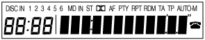
Diagnostic Assist Function
Information display
ac9uun00000508
|
Speaker
Radio
acxuun00000371
|
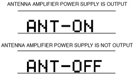
Antenna control condition
acxuun00000573
|