 |
ac9uuw00000571
INSTRUMENT CLUSTER INSPECTION
id092200800400
Speedometer
Using the input/output check mode
1. Inspect the speedometer by setting it to check code 12 of the input/output check mode. (See INSTRUMENT CLUSTER INPUT/OUTPUT CHECK MODE.)
Using a speedometer tester
1. Adjust the tire pressure to the specification.
2. Using a speedometer tester, verify that the tester reading is as indicated in the table below.
|
Speedometer tester indication (km/h) |
Allowable range (km/h) |
|---|---|
|
20
|
20—25
|
|
40
|
40—45
|
|
60
|
60—65
|
|
80
|
80—86
|
|
100
|
100—107
|
|
120
|
120—128
|
|
140
|
140—148
|
3. Verify that the speedometer reading is within the range indicated in the table.
Tachometer
Using the input/output check mode
1. Inspect the tachometer by setting it to check code 13 of the input/output check mode. (See INSTRUMENT CLUSTER INPUT/OUTPUT CHECK MODE.)
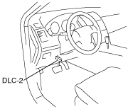
Using M-MDS
1. Connect the M-MDS to the DLC‐2.
ac9uuw00000571
|
2. After the vehicle is identified, select the following items from the initialization screen of the M-MDS.
3. Compare the data monitor item (IC_TACHO) with the tachometer indication.
Fuel gauge
1. Inspect the fuel gauge by setting it to check code 23 of the input/output check mode. (See INSTRUMENT CLUSTER INPUT/OUTPUT CHECK MODE.)
Water temperature gauge
1. Inspect the water temperature gauge by setting it to check code 25 of the input/output check mode. (See INSTRUMENT CLUSTER INPUT/OUTPUT CHECK MODE.)