 |
acxuun00000506
CAN SYSTEM DESCRIPTION
id094000101000
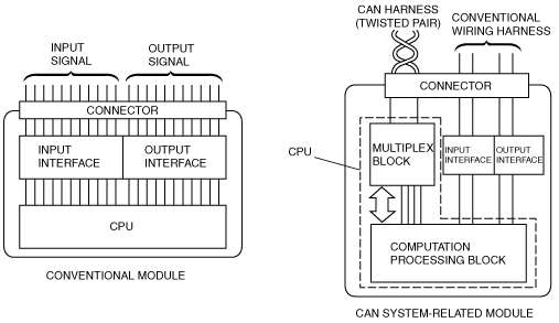
Mechanism of CAN System-Related Module
|
Component |
Function |
|
|---|---|---|
|
Electrical circuit
|
Supplies power to CPU and vicinity, and to input/output interface.
|
|
|
CPU
|
Computation processing block
|
Control function has been expanded, and when transmission is necessary, transmitted data is stored in a multiplex block. If a multiplex block receives a request to read stored data, transmitted data is read from the multiplex block.
|
|
Multiplex block
|
Transmits data received from bus line to computation processing block. In addition, sends transmitted data stored from computation processing block to bus line.
|
|
|
Input/Output interface
|
Electrically converts information signals from switches to, be input to CPU, and signals output from CPU for operating actuator or indicator lights.
|
|
acxuun00000506
|
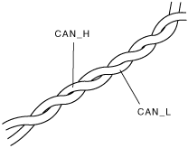
Twisted Pair
acxuun00000507
|
Time Division Multiplex
acxuun00000508
|
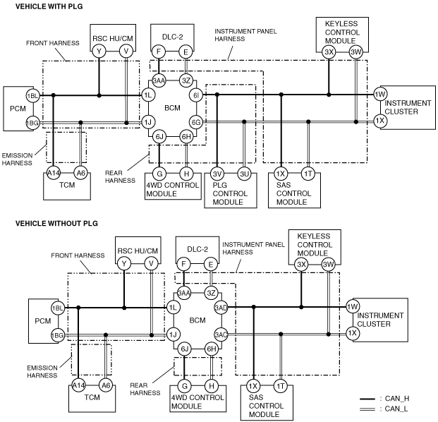
Vehicle CAN System
acxuun00000509
|
CAN Signal-Chart (HS-CAN)
|
Signal |
Multiplex module |
|||||||||
|---|---|---|---|---|---|---|---|---|---|---|
|
PCM |
TCM |
DSC/RSC HU/CM |
BCM |
4WD control module |
PLG control module |
SAS control module |
Keyless control module |
Instrument cluster |
Engine-off-natural-vacuum |
|
|
Immobilizer-related information
|
OUT
|
–
|
–
|
–
|
–
|
–
|
–
|
IN
|
IN
|
–
|
|
IN
|
–
|
–
|
–
|
–
|
–
|
–
|
OUT
|
–
|
–
|
|
|
Engine torque
|
OUT
|
IN
|
–
|
–
|
–
|
–
|
–
|
–
|
–
|
–
|
|
Engine load
|
OUT
|
IN
|
–
|
–
|
–
|
–
|
–
|
–
|
–
|
–
|
|
Engine torque
|
OUT
|
–
|
IN
|
–
|
–
|
–
|
–
|
–
|
–
|
–
|
|
OUT
|
IN
|
–
|
–
|
–
|
–
|
–
|
–
|
–
|
–
|
|
|
Brake switch
|
OUT
|
–
|
IN
|
–
|
–
|
–
|
–
|
–
|
–
|
–
|
|
Malfunction of evaporative emission control system-related information
|
OUT
|
–
|
–
|
–
|
–
|
–
|
–
|
–
|
–
|
IN
|
|
IN
|
–
|
–
|
–
|
–
|
–
|
–
|
–
|
–
|
OUT
|
|
|
FUEL_FLOW
|
OUT
|
–
|
–
|
–
|
–
|
–
|
–
|
–
|
IN
|
–
|
|
MIL on request
|
OUT
|
–
|
–
|
–
|
–
|
–
|
–
|
–
|
IN
|
–
|
|
IN
|
OUT
|
–
|
–
|
–
|
–
|
–
|
–
|
–
|
–
|
|
|
Cruise control system-related information
|
OUT
|
–
|
–
|
–
|
–
|
–
|
–
|
–
|
IN
|
–
|
|
OUT
|
–
|
IN
|
–
|
–
|
–
|
–
|
–
|
IN
|
–
|
|
|
ETC warning light on request
|
OUT
|
–
|
–
|
–
|
–
|
–
|
–
|
–
|
IN
|
–
|
|
Electronic throttle control (ETC) status
|
OUT
|
–
|
–
|
–
|
–
|
–
|
–
|
–
|
IN
|
–
|
|
Generator warning light on request
|
OUT
|
–
|
–
|
–
|
–
|
–
|
–
|
–
|
IN
|
–
|
|
Fuel cap warning light on request
|
OUT
|
–
|
–
|
–
|
–
|
–
|
–
|
–
|
IN
|
–
|
|
Intake air temperature
|
OUT
|
–
|
IN
|
–
|
–
|
–
|
–
|
–
|
–
|
–
|
|
Engine coolant temperature
|
OUT
|
IN
|
–
|
–
|
–
|
–
|
–
|
–
|
–
|
–
|
|
ATX gear position/selector lever position
|
OUT
|
–
|
IN
|
–
|
–
|
–
|
–
|
–
|
–
|
–
|
|
Steering angle/steering angle sensor status
|
–
|
–
|
IN
|
OUT
|
–
|
–
|
–
|
–
|
–
|
–
|
|
Door switch status (LF, RF, LR, RR, liftgate)
|
–
|
–
|
IN
|
OUT
|
–
|
–
|
–
|
–
|
IN
|
–
|
|
Key reminder switch status
|
–
|
–
|
–
|
OUT
|
–
|
–
|
–
|
–
|
IN
|
–
|
|
Turn indicator light on request
|
–
|
–
|
–
|
OUT
|
–
|
–
|
–
|
–
|
IN
|
–
|
|
Turn indicator light on request
|
–
|
–
|
–
|
OUT
|
–
|
–
|
–
|
–
|
IN
|
–
|
|
Brake fluid level
|
–
|
–
|
–
|
OUT
|
–
|
–
|
–
|
–
|
IN
|
–
|
|
Oil pressure switch status
|
–
|
–
|
–
|
OUT
|
–
|
–
|
–
|
–
|
IN
|
–
|
|
Washer fluid level sensor status
|
–
|
–
|
–
|
OUT
|
–
|
–
|
–
|
–
|
IN
|
–
|
|
Door lock status
|
–
|
–
|
–
|
OUT
|
–
|
IN
|
–
|
–
|
–
|
–
|
|
Torque down request
|
IN
|
OUT
|
–
|
–
|
–
|
–
|
–
|
–
|
–
|
–
|
|
ATF temperature
|
IN
|
OUT
|
–
|
–
|
–
|
–
|
–
|
–
|
–
|
–
|
|
ATX gear position/selector lever position
|
–
|
OUT
|
–
|
–
|
–
|
–
|
–
|
–
|
IN
|
–
|
|
Travelled distance
|
–
|
OUT
|
–
|
–
|
–
|
–
|
–
|
–
|
IN
|
–
|
|
Brake fluid pressure
|
–
|
IN
|
OUT
|
–
|
–
|
–
|
–
|
–
|
–
|
–
|
|
Torque down request
|
IN
|
–
|
OUT
|
–
|
–
|
–
|
–
|
–
|
–
|
–
|
|
Brake system status (EBD/ABS/DSC/RSC)
|
–
|
IN
|
OUT
|
–
|
–
|
–
|
–
|
–
|
–
|
–
|
|
IN
|
IN
|
OUT
|
–
|
–
|
–
|
–
|
–
|
–
|
–
|
|
|
IN
|
–
|
OUT
|
–
|
–
|
–
|
–
|
–
|
–
|
–
|
|
|
–
|
–
|
OUT
|
–
|
–
|
–
|
–
|
–
|
IN
|
–
|
|
|
Wheel speed (LF, RF, LR, RR)
|
IN
|
IN
|
OUT
|
IN
|
IN
|
IN
|
–
|
–
|
–
|
–
|
|
IN
|
IN
|
OUT
|
IN
|
IN
|
–
|
–
|
–
|
–
|
–
|
|
|
Brake system warning light on request
|
–
|
–
|
OUT
|
–
|
–
|
–
|
–
|
–
|
IN
|
–
|
|
ABS warning light on request
|
–
|
–
|
OUT
|
–
|
–
|
–
|
–
|
–
|
IN
|
–
|
|
Tire circumference (front/rear)
|
IN
|
–
|
OUT
|
–
|
–
|
–
|
–
|
–
|
–
|
–
|
|
DSC indicator light on request
|
–
|
–
|
OUT
|
–
|
–
|
–
|
–
|
–
|
IN
|
–
|
|
TCS OFF light on request
|
–
|
–
|
OUT
|
–
|
–
|
–
|
–
|
–
|
IN
|
–
|
|
Security light on request
|
–
|
–
|
–
|
–
|
–
|
–
|
–
|
OUT
|
IN
|
–
|
|
Keyless warning buzzer on request
|
–
|
–
|
–
|
–
|
–
|
–
|
–
|
OUT
|
IN
|
–
|
|
Keyless indicator light on request
|
–
|
–
|
–
|
–
|
–
|
–
|
–
|
OUT
|
IN
|
–
|
|
Keyless warning light on request
|
–
|
–
|
–
|
–
|
–
|
–
|
–
|
OUT
|
–
|
–
|
|
PLG operation request
|
–
|
–
|
–
|
–
|
–
|
IN
|
–
|
OUT
|
–
|
–
|
|
–
|
–
|
–
|
IN
|
–
|
OUT
|
–
|
–
|
–
|
–
|
|
|
–
|
–
|
–
|
IN
|
–
|
OUT
|
–
|
IN
|
IN
|
–
|
|
|
Buckle switch status
|
–
|
–
|
–
|
–
|
–
|
–
|
OUT
|
–
|
IN
|
–
|
|
Passenger sensing system status
|
–
|
–
|
–
|
–
|
–
|
–
|
OUT
|
–
|
IN
|
–
|
|
Air bag system warning light on request
|
–
|
–
|
–
|
–
|
–
|
–
|
OUT
|
–
|
IN
|
–
|
|
–
|
–
|
–
|
–
|
–
|
–
|
IN
|
–
|
OUT
|
–
|
|
|
Air bag system warning buzzer on status
|
–
|
–
|
–
|
–
|
–
|
–
|
OUT
|
–
|
IN
|
–
|
|
4WD system status
|
–
|
–
|
IN
|
–
|
OUT
|
–
|
–
|
–
|
–
|
–
|
|
–
|
–
|
–
|
–
|
OUT
|
–
|
–
|
–
|
IN
|
–
|
|
|
Fuel tank level
|
IN
|
–
|
–
|
–
|
–
|
–
|
–
|
–
|
OUT
|
IN
|
|
IN
|
–
|
–
|
–
|
–
|
–
|
–
|
–
|
OUT
|
–
|
|
|
Brake fluid level
|
–
|
–
|
IN
|
–
|
–
|
–
|
–
|
–
|
OUT
|
–
|
|
Parking brake switch status
|
IN
|
–
|
IN
|
–
|
IN
|
–
|
–
|
–
|
OUT
|
–
|
|
Ignition key position
|
IN
|
–
|
IN
|
–
|
–
|
–
|
–
|
–
|
OUT
|
–
|
CAN Signal-Chart (MS-CAN)
|
Signal |
Multiplex module |
||
|---|---|---|---|
|
Audio unit |
Audio amplifier |
Information display |
|
|
Audio status display request
|
OUT
|
–
|
IN
|
|
Ignition key position
|
OUT
|
–
|
IN
|
|
Drive information system data
|
OUT
|
–
|
IN
|
|
Buttons status
|
OUT
|
–
|
IN
|
|
Vehicle speed
|
OUT
|
IN
|
–
|
|
Audio system-related information
|
OUT
|
IN
|
–
|
|
IN
|
OUT
|
–
|
|
|
Beep sound request
|
IN
|
IN
|
OUT
|
On-Board Diagnostic Function
Block diagram
HS-CAN
ac9wzn00000166
|
MS-CAN
ac9wzn00000167
|
Failure detection function
Fail-safe function
Memory function
Self-malfunction diagnostic function
DTC table
|
DTC |
Malfunction location |
DTC output module |
|---|---|---|
|
U0073
|
CAN system communication error
|
• TCM
• DSC/RSC HU/CM
• BCM
• 4WD control module
• PLG control module
• SAS control module
• Keyless control module
• Instrument cluster
|
|
U0100
|
Communication error to PCM
|
• TCM
• DSC/RSC HU/CM
• 4WD control module
• PLG control module
• SAS control module
• Keyless control module
• Instrument cluster
|
|
U0101
|
Communication error to TCM
|
• PCM
• 4WD control module
• PLG control module
• Instrument cluster
|
|
U0114
|
Communication error to 4WD control module
|
• Instrument cluster
|
|
U0121
|
Communication error to DSC/RSC HU/CM
|
• TCM
• 4WD control module
• Instrument cluster
|
|
U0129
|
Communication error to DSC/RSC HU/CM
|
• PCM
|
|
U0140
|
Communication error to BCM
|
• TCM
• DSC/RSC HU/CM
• PLG control module
• Keyless control module
• Instrument cluster
|
|
U0151
|
Communication error to SAS control module
|
Instrument cluster
|
|
U0155
|
Communication error to instrument cluster
|
• PCM
• DSC/RSC HU/CM
• 4WD control module
• PLG control module
• SAS control module
|
|
U0184
|
Communication error to audio unit
|
Information display
|
|
U0214
|
Communication error to keyless control module
|
• PLG control module
• Instrument cluster
|
|
U0300
|
Internal control module software incompatibility
|
PCM
|
|
U0323
|
Communication error to instrument cluster
|
Keyless control module
|
|
U0415
|
Abnormal message from DSC/RSC HU/CM
|
TCM
|
|
U2023
|
Abnormal message from other modules
|
• DSC/RSC HU/CM
• Keyless control module
• Instrument cluster
|
|
U2510
|
Communication error to PCM
|
Instrument cluster
|
|
U2516
|
CAN system communication error
|
Information display
|
|
23:Er11
|
Communication error to audio amplifier
|
Audio unit (Touch panel type)
|
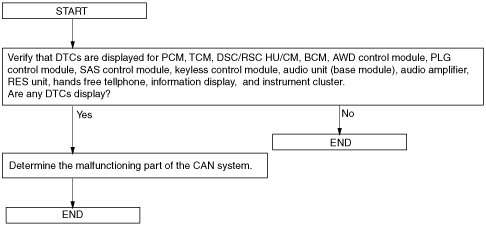
Narrowing down malfunction locations
Flowchart
ac9uun00000374
|
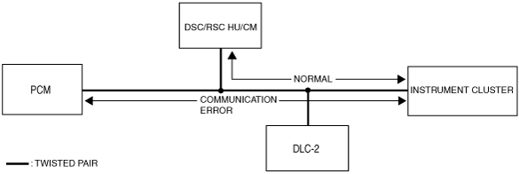
Example (PCM-related communication error)
1. DTCs for the PCM, DSC/RSC HU/CM and instrument cluster can be verified using the Mazda Modular Diagnostic System (M-MDS).
|
Module |
Displayed DTC |
Probable malfunction location |
|---|---|---|
|
PCM
|
U0155
|
Communication error between PCM and instrument cluster
|
|
DSC/RSC HU/CM
|
–
|
–
|
|
Instrument cluster
|
U0100
|
Communication error between instrument cluster and PCM
|
ac9uun00000373
|
2. If there is a communication error between the instrument cluster and PCM, even if the communication between the DSC/RSC HU/CM and the instrument cluster is normal, it is probable that there is a malfunction in the PCM or PCM-related wiring harnesses.