GENERATOR CONSTRUCTION [MZI-3.7]
id0117d2102300
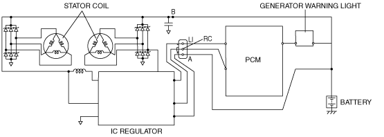
• An IC regulator is built into the generator which determines the control voltage according to the duty signal sent from the PCM to generator, and controls output.
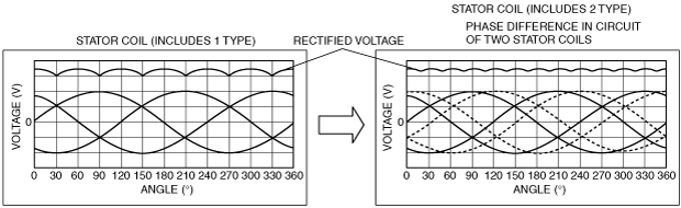
• Two delta connection type stator coils have been adopted.
Terminal B circuit
• Generator output is supplied to the battery from terminal B, and to each electronic device.
Terminal RC circuit
• The terminal RC circuit is the circuit where the duty signal (Generator Regulator Control (GENRC) signal) from the PCM is input to the IC regulator. The IC regulator control voltage is determined according to the GENRC signal.
Terminal LI circuit
• The terminal LI circuit outputs the duty signal (Generator Load Input (GENLI) signal) of the field coil to the PCM. The GENLI signal is used as the feedback signal which corresponds to the GENRC signal input from the PCM. The PCM changes the duty value of the GENRC signal according to the GENLI signal. If the output is not normal, a 0% duty value is output to the PCM which then illuminates the generator warning light.
Terminal A circuit
• Terminal A circuit is used to detect battery voltage. This voltage is used to determine generator output voltage. This circuit is used to supply current to the field coil (rotor). The amount of current supplied to the field coil (rotor) determines the generator output current.
• The phase difference in the circuit of the two stator coils causes the electromagnetic pull between the rotor and the stator to be eliminated logically. Due to this, electromagnetic vibration and generator operation noise (electromagnetic noise) have been reduced.
• The pulsation occurring through voltage rectifying is minimized, as a result, stable voltage output is supplied due to the adoption of two stator coils with the phase difference.
• If there is malfunction in the charging system, the generator warning light in the instrument cluster illuminates.