 |
ac9wzw00000827
JOINT SHAFT REMOVAL/INSTALLATION [2WD]
id0313008009a3
1. Remove the side cover.
2. Remove the front ABS wheel-speed sensor. (See FRONT ABS WHEEL-SPEED SENSOR REMOVAL/INSTALLATION.)
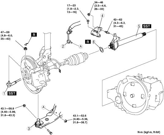
3. Remove in the order indicated in the table.
4. Install in the reverse order of removal.
ac9wzw00000827
|
|
1
|
Tie-rod end ball joint
|
|
2
|
Stabilizer control link (lower side)
|
|
3
|
Lower arm ball joint
|
|
4
|
Bracket
|
|
5
|
Joint shaft
(See Joint Shaft Removal Note.)
|
|
6
|
Joint shaft clip
|
Joint Shaft Removal Note
1. Separate the right side drive shaft from the joint shaft by using the SSTs.
ac9uuw00002440
|
2. Remove the bolts.
3. Pull the joint shaft straight out.
Joint Shaft Clip Installation Note
1. Install a new clip onto the joint shaft with the opening facing upward. Ensure that the diameter of the clip does not exceed the specification on installation.
2. After installation, measure the outer diameter. If it exceeds the specification, repeat Step 1 using a new clip.
ac9uuw00001338
|
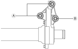
Joint Shaft Installation Note
1. Insert the joint shaft into the transaxle.
2. Temporarily tighten the bolts A and B.
ac9wzw00000845
|
3. Tighten the bolts A, then tighten the bolt B to the specified torque.