 |
ac9uuw00002010
INTERLOCK CABLE ADJUSTMENT
id051800800300
1. Turn the ignition switch to the ON position. (Engine off)
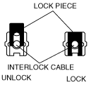
2. Pull up the lock piece of the interlock cable to release the lock.
ac9uuw00002010
|
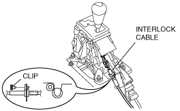
3. Remove the clip of the selector lever base plate, then remove the interlock cable from the U-groove.
L.H.D.
ac9wzw00000603
|
R.H.D.
ac9wzw00000604
|
4. Remove the interlock cable from the selector lever.
5. Remove the lock unit from the bracket.
L.H.D.
ac9uuw00002011
|
R.H.D.
ac9wzw00000023
|
6. Verify that the marking on the slider pin is positioned as shown in the figure.
ac9wzw00000024
|
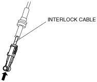
7. Push the interlock cable.
ac9uuw00002013
|
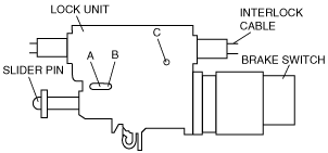
8. Insert a 1.5mm {0.059 in} round bar or similar into hole A with the slider pin fully pushed in.
ac9uuw00002014
|
9. Fully pull the end of the interlock cable.
ac9uuw00002015
|
10. Push a 1.5mm {0.059 in} round bar or similar into hole B and hole C of the lock unit until it passes through.
ac9uuw00002014
|
11. Disconnect the brake switch connector.
12. Remove the brake switch. (See BRAKE PEDAL REMOVAL/INSTALLATION [L.H.D.].)(See BRAKE PEDAL REMOVAL/INSTALLATION [R.H.D.].)
13. Install a new brake switch. (See BRAKE PEDAL REMOVAL/INSTALLATION [L.H.D.].)(See BRAKE PEDAL REMOVAL/INSTALLATION [R.H.D.].)
14. Install the lock unit to the bracket. (See SELECTOR LEVER COMPONENT REMOVAL/INSTALLATION.)
15. Rotate the slider pin to release the lock and verify that it slides freely.
16. Verify that the slider pin contacts the brake pedal stopper rubber and rotate the slider pin to lock.
ac9wzw00000025
|
17. Install the interlock cable end to the interlock link on the selector lever.
L.H.D.
ac9wzw00000603
|
R.H.D.
ac9wzw00000604
|
18. Fit the interlock cable in the U-groove in the selector lever base plate and install the clip.
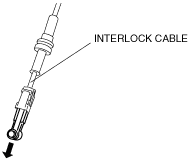
19. Press the interlock cable lock piece in until it is locked.
ac9uuw00002018
|
20. Remove a 1.5mm {0.059 in} round bar or similar from the lock unit holes A, B, and C.
ac9uuw00002014
|
21. Connect the brake switch connector with the brake pedal released.
22. Inspect shift lock operation. (See SHIFT-LOCK INSPECTION.)