|
ac9wzw00000560
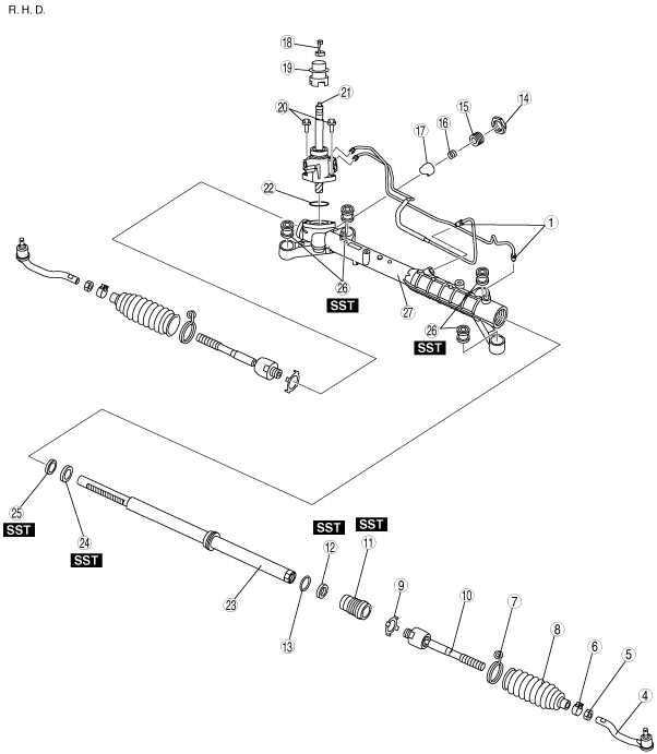
STEERING GEAR AND LINKAGE DISASSEMBLY
id061400801000
1. Disassemble in the order indicated in the table.
ac9wzw00000560
|
ac9wzw00000561
|
|
1
|
Oil pipe
|
|
2
|
Return pipe (L.H.D. only)
|
|
3
|
O-ring (L.H.D. only)
|
|
4
|
Tie-rod end
(See Tie-rod End Disassembly Note.)
|
|
5
|
Locknut
|
|
6
|
Boot clamp
|
|
7
|
Boot band
|
|
8
|
Boot
|
|
9
|
Lock washer (If equipped.)
|
|
10
|
Tie rod
|
|
11
|
Holder
|
|
12
|
Oil seal (holder side)
|
|
13
|
O-ring
|
|
14
|
Locknut (adjusting cover)
|
|
15
|
Adjusting cover
|
|
16
|
Yoke spring
|
|
17
|
Support yoke
|
|
18
|
Clip
|
|
19
|
Pinion plug
|
|
20
|
Bolt
|
|
21
|
Pinion shaft component
|
|
22
|
O-ring
|
|
23
|
Steering rack
|
|
24
|
Oil seal (gear housing side)
|
|
25
|
Inner guide
|
|
26
|
Mounting rubber
|
|
27
|
Gear housing
|
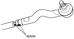
Tie-rod End Disassembly Note
1. Place alignment marks as shown in the figure for proper installation.
ac9uuw00001855
|
Lock Washer, Tie Rod Disassembly Note
1. Unclamp the washer.
2. Lock the steering rack end against rotation with a wrench and remove the tie rod.
ac9uuw00001856
|
3. Remove the lock washer.
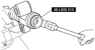
Holder, Oil Seal (Holder Side) Disassembly Note
1. Remove the holder from the gear housing using the SST.
ac9uuw00001857
|
2. Remove the oil seal from the holder using the SST and a press.
ac9uuw00001858
|
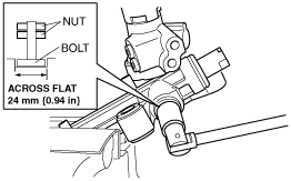
Adjusting Cover Disassembly Note
1. Install two nuts to the bolt across a flat 24 mm {0.94 in} and tighten them using a wrench.
ac9uuw00001859
|
2. Disassemble the adjusting cover with the bolt and nuts created in Step 1.
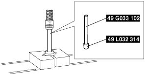
Oil Seal (Gear Housing Side), Inner Guide Disassembly Note
1. Set the SSTs as shown.
2. Insert the SSTs from the valve housing side.
3. Remove the oil seal (gear housing side) and inner guide using a press.
ac9uuw00001860
|
Mounting Rubber Disassembly Note
1. Press the mounting rubber out from the gear housing using the SSTs and a press.
ac9uuw00001922
|