 |
ac9wzw00000562
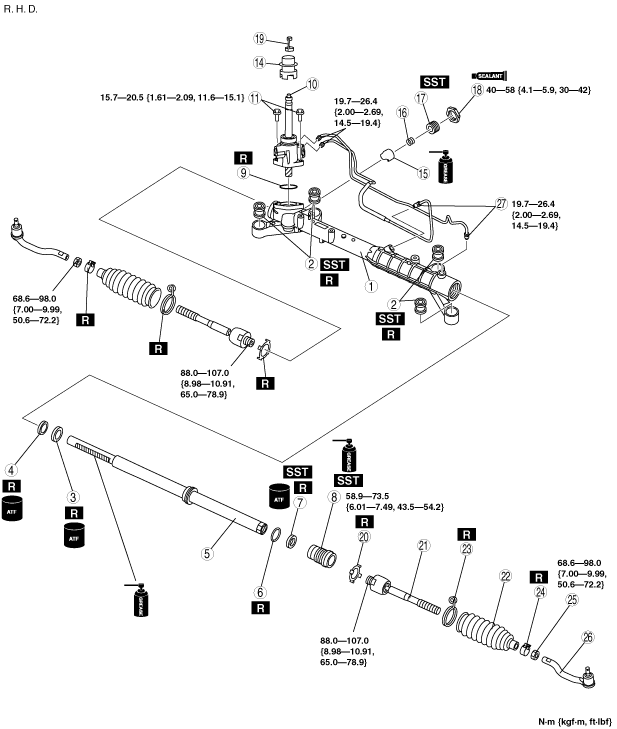
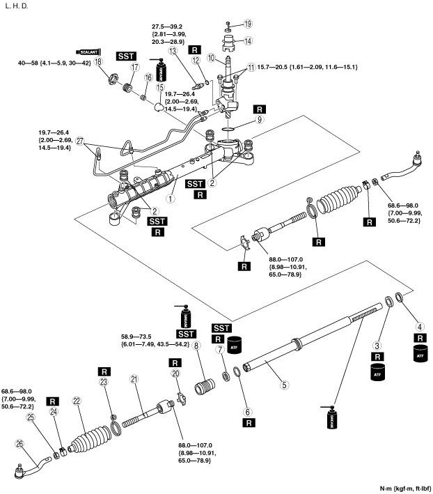
STEERING GEAR AND LINKAGE ASSEMBLY
id061400801200
1. Assemble in the order indicated in the table.
ac9wzw00000562
|
ac9wzw00000563
|
|
1
|
Gear housing
|
|
2
|
Mounting rubber
|
|
3
|
Oil seal (gear housing side)
|
|
4
|
Inner guide
|
|
5
|
Steering rack
|
|
6
|
O-ring
|
|
7
|
Oil seal (holder side)
|
|
8
|
Holder
(See Holder Assembly Note.)
|
|
9
|
O-ring
|
|
10
|
Pinion shaft component
|
|
11
|
Bolt
|
|
12
|
O-ring (L.H.D. only)
|
|
13
|
Return pipe (L.H.D. only)
|
|
14
|
Pinion plug
|
|
15
|
Support yoke
|
|
16
|
Yoke spring
|
|
17
|
Adjusting cover
|
|
18
|
Locknut (adjusting cover)
|
|
19
|
Clip
|
|
20
|
Lock washer (If equipped.)
|
|
21
|
Tie rod
|
|
22
|
Boot
|
|
23
|
Boot band
|
|
24
|
Boot clamp
|
|
25
|
Locknut
|
|
26
|
Tie-rod end
|
|
27
|
Oil pipe
|
Mounting Rubber Assembly Note
1. Apply soapy water to the rubber part of the mounting rubber.
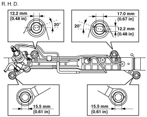
2. Temporarily install the gear housing so that the mounting rubber is positioned as shown in the figure.
ac9wzw00001018
|
ac9wzw00001019
|
3. Press the mounting rubber until the mounting rubber end comes out completely from the gear housing using the SSTs and a press.
ac9uuw00001923
|
4. Reverse the gear housing, then press the mounting rubber until the mounting rubber end comes out completely from the other side. At this time, the mounting rubber end and steel pipe are aligned.
ac9uuw00002147
|
Steering Rack, Oil Seal (Gear Housing Side), Inner Guide Assembly Note
1. Apply multi-purpose grease to the oil seal (gear housing side) and Inner guide.
2. Install the plastic bag to the steering rack teeth so as not to damage the oil seal (gear housing side) and the inner guide, and install the oil seal (gear housing side) and the inner guide to the seal. Move the oil seal (gear housing side) and the inner guide together with the plastic bag so that they pass the steering rack teeth, then remove the plastic bag.
ac9uuw00001902
|
3. Put the steering rack into the gear housing.
4. Using a press, press-in the oil seal (gear housing side) and inner guide until the press-in force increases rapidly.
Oil Seal (Holder Side) Assembly Note
1. Assemble the oil seal (holder side) to the holder using a press and the SST.
ac9uuw00001866
|
Holder Assembly Note
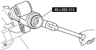
1. Assemble the holder to the gear housing using the SST.
ac9uuw00001867
|
2. Connect the SSTs to the power cylinder section of the gear housing.
3. Apply 53.3 kPa {400 mmHg, 15.7 inHg}vacuum with a vacuum pump and verify that it is held for at least 30 seconds.
ac9uuw00001868
|
4. If the vacuum is not held, replace the oil seal.
Adjusting Cover Assembly Note
1. Set the rack to the center position.
2. Install two nuts to the bolt across a flat 24 mm {0.94 in} and tighten them using a wrench.
3. Assemble the adjusting cover with the bolt and nuts created in Step 1.
ac9uuw00001869
|
4. Tighten the adjusting cover to 19.6 N·m {2.0 kgf·m, 15 ft·lbf}.
5. Slide the rack back and forth 60 mm {2.4 in} three times.
6. Retighten the adjusting cover to 19.6 N·m {2.0 kgf·m, 15 ft·lbf}.
7. Loosen the adjusting cover 63° using the SST.
ac9uuw00001870
|
8. Hold the adjusting cover so as not to rotate and tighten the locknut.
ac9uuw00001871
|
9. Measure the pinion torque using the SST and pull scale. (Measurement speed: 0.5—2.0 rpm)
10. If not within the specification, repeat Step 4 to 9.
Lock Washer, Tie Rod Assembly Note
1. Temporary assemble the lock washer and the tie rod to the steering rack.
2. Lock the steering rack end against rotation with a wrench and assemble the tie rod.
ac9uuw00001872
|
3. Clamp the lock washer.