 |
ac9uuw00001030
MAGNETIC CLUTCH DISASSEMBLY/ASSEMBLY
id074000800400
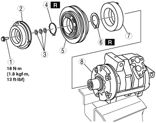
1. Disassemble in the order indicated in the table.
ac9uuw00001030
|
|
1
|
Bolt
|
|
2
|
Pressure plate
|
|
3
|
Shim
|
|
4
|
Snap ring
|
|
5
|
A/C compressor pulley
|
|
6
|
Snap ring
(See Snap Ring Installation Note.)
|
|
7
|
Stator
|
|
8
|
A/C compressor body
|
2. Assemble in the reverse order of disassembly.
3. Inspect the magnetic clutch clearance. (See MAGNETIC CLUTCH CLEARANCE INSPECTION.)
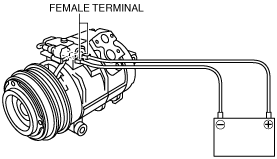
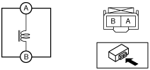
Bolt Removal/Installation Note
1. When removing or installing the bolt, lock the A/C compressor pulley against rotation using the following procedure.
ac9uuw00003003
|
ac9uuw00002468
|
ac9uuw00003004
|
Snap Ring Installation Note
1. Install the snap ring so that the tapered area is on the pressure plate side.
ac9wzw00002797
|