|
1
|
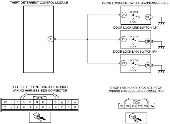
INSPECT FRONT DOOR LATCH AND LOCK ACTUATOR (PASSENGER-SIDE) CONNECTOR AND TERMINALS
• Turn the ignition switch to the OFF position.
• Disconnect the negative battery cable.
• Disconnect the front door latch and lock actuator (passenger-side) connector.
• Inspect the connector and terminals (corrosion, damage, pin disconnection).
• Is there any malfunction?
|
Yes
|
Repair or replace the connector or terminals, then go to Step 15.
|
|
No
|
Go to the next step.
|
|
2
|
DETERMINE MALFUNCTIONING LOCATION
• Reconnect the negative battery cable.
• Turn the ignition switch to the ON position.
• Measure the voltage at the front door latch and lock actuator (passenger-side) terminal 2A (wiring harness-side).
• Is there any voltage?
|
Yes
|
Go to the next step.
|
|
No
|
Go to Step 13.
|
|
3
|
INSPECT DOOR LOCK-LINK SWITCH (PASSENGER-SIDE) GROUND CIRCUIT FOR OPEN CIRCUIT
• Turn the ignition switch to the OFF position.
• Disconnect the negative battery cable.
• Inspect for continuity between front door latch and lock actuator (passenger-side) terminal 2E (wiring harness-side) and body ground.
• Is there continuity?
|
Yes
|
Go to the next step.
|
|
No
|
Repair or replace the wiring harness for a possible open circuit, then go to Step 15.
|
|
4
|
INSPECT DOOR LOCK-LINK SWITCH (PASSENGER-SIDE)
• Inspect the door lock-link switch (passenger-side).
• Is there any malfunction?
|
Yes
|
Replace the front door latch and lock actuator (passenger-side), then go to Step 15.
|
|
No
|
Go to the next step.
|
|
5
|
INSPECT REAR DOOR LATCH AND LOCK ACTUATOR (LH) CONNECTOR AND TERMINALS
• Disconnect the rear door latch and lock actuator (LH) connector.
• Inspect the connector and terminals (corrosion, damage, pin disconnection).
• Is there any malfunction?
|
Yes
|
Repair or replace the connector or terminals, then go to Step 15.
|
|
No
|
Go to the next step.
|
|
6
|
DETERMINE MALFUNCTIONING LOCATION
• Reconnect the negative battery cable.
• Turn the ignition switch to the ON position.
• Measure the voltage at the rear door latch and lock actuator (LH) terminal 2F (wiring harness-side).
• Is there any voltage?
|
Yes
|
Go to the next step.
|
|
No
|
Go to Step 13.
|
|
7
|
INSPECT DOOR LOCK-LINK SWITCH (LH) GROUND CIRCUIT FOR OPEN CIRCUIT
• Turn the ignition switch to the OFF position.
• Disconnect the negative battery cable.
• Inspect for continuity between rear door latch and lock actuator (LH) terminal 2B (wiring harness-side) and body ground.
• Is there continuity?
|
Yes
|
Go to the next step.
|
|
No
|
Repair or replace the wiring harness for a possible open circuit, then go to Step 15.
|
|
8
|
INSPECT DOOR LOCK-LINK SWITCH (LH)
• Inspect the door lock-link switch (LH).
• Is there any malfunction?
|
Yes
|
Replace the rear door latch and lock actuator (LH), then go to Step 15.
|
|
No
|
Go to the next step.
|
|
9
|
INSPECT REAR DOOR LATCH AND LOCK ACTUATOR (RH) CONNECTOR AND TERMINALS
• Disconnect the rear door latch and lock actuator (RH) connector.
• Inspect the connector and terminals (corrosion, damage, pin disconnection).
• Is there any malfunction?
|
Yes
|
Repair or replace the connector or terminals, then go to Step 15.
|
|
No
|
Go to the next step.
|
|
10
|
DETERMINE MALFUNCTIONING LOCATION
• Reconnect the negative battery cable.
• Turn the ignition switch to the ON position.
• Measure the voltage at the rear door latch and lock actuator (RH) terminal 2A (wiring harness-side).
• Is there any voltage?
|
Yes
|
Go to the next step.
|
|
No
|
Go to Step 13.
|
|
11
|
INSPECT DOOR LOCK-LINK SWITCH (RH) GROUND CIRCUIT FOR OPEN CIRCUIT
• Turn the ignition switch to the OFF position.
• Disconnect the negative battery cable.
• Inspect for continuity between rear door latch and lock actuator (RH) terminal 2E (wiring harness-side) and body ground.
• Is there continuity?
|
Yes
|
Go to the next step.
|
|
No
|
Repair or replace the wiring harness for a possible open circuit, then go to Step 15.
|
|
12
|
INSPECT DOOR LOCK-LINK SWITCH (RH)
• Inspect the door lock-link switch (RH).
• Is there any malfunction?
|
Yes
|
Replace the rear door latch and lock actuator (RH), then go to Step 15.
|
|
No
|
Go to the next step.
|
|
13
|
INSPECT THEFT-DETERRENT CONTROL MODULE CONNECTOR AND TERMINALS
• Turn the ignition switch to the OFF position.
• Disconnect the negative battery cable.
• Disconnect the theft-deterrent control module connector.
• Inspect the connector and terminals (corrosion, damage, pin disconnection).
• Is there any malfunction?
|
Yes
|
Repair or replace the connector or terminals, then go to Step 15.
|
|
No
|
Go to the next step.
|
|
14
|
DETERMINE MALFUNCTIONING LOCATION
• Reconnect the theft-deterrent control module connector.
• Reconnect the negative battery cable.
• Turn the ignition switch to the ON position.
• Measure the voltage at the theft-deterrent control module terminal T (wiring harness-side).
• Is there any voltage?
|
Yes
|
Repair or replace the wiring harness for a possible open circuit, then go to the next step.
|
|
No
|
Go to the next step.
|
|
15
|
VERIFY TROUBLESHOOTING COMPLETED
• Make sure to reconnect the disconnected connectors.
• Reconnect the negative battery cable.
• Clear the DTC using the M-MDS.
• Perform the theft-deterrent control module DTC inspection using the M-MDS with the door (passenger-side/LH/RH) closed.
• Is the same DTC present?
|
Yes
|
Repeat the inspection from Step 1.
• If the malfunction recurs, replace the theft-deterrent control module.
Go to the next step.
|
|
No
|
Go to the next step.
|
|
16
|
VERIFY THAT NO OTHER DTCs ARE PRESENT
• Are any DTCs present?
|
Yes
|
Go to the applicable DTC inspection.
|
|
No
|
DTC troubleshooting completed.
|