FOREWORD [MULTIPLEX COMMUNICATION SYSTEM (L.H.D.)]


id0902j3845700

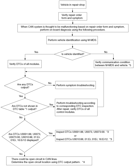
•  If the CAN system is considered to be the cause of the malfunction based on the repair order form and the malfunctioning symptom, follow the Troubleshooting Procedure. (See Troubleshooting Procedure.)
•  DTCs are also output due to a control module or sensor malfunction, or incorrect power supply. Verify the output DTCs and first inspect the DTCs not shown in DTC TABLE. (See DTC TABLE [MULTIPLEX COMMUNICATION SYSTEM (L.H.D.)].)
•  If there is an open circuit in the communication lines, it is possible that signal error DTCs may be output in addition to communication error DTCs. Perform DETERMINING MALFUNCTIONING PART if the communication error and signal error DTCs are output simultaneously. (See DETERMINING MALFUNCTIONING PART (HS-CAN) [MULTIPLEX COMMUNICATION SYSTEM (L.H.D.)].) (See DETERMINING MALFUNCTIONING PART (MS-CAN) [MULTIPLEX COMMUNICATION SYSTEM (L.H.D.)].)
•  If the network test is performed and “BSM Fail” is displayed on the M-MDS, after repair is completed, complete the session and perform the network test again. (with blind spot monitoring (BSM) control module connector 10-pin type)

Troubleshooting Procedure

ac9wzw00002765
*1  :(See DTC TABLE [MULTIPLEX COMMUNICATION SYSTEM (L.H.D.)].)
*2  :(See DTC U0001:88, U0073, U0073:00 [MULTIPLEX COMMUNICATION SYSTEM (L.H.D.)].)
*3  :(See DTC U0010:88, 01:Er, 01Er, 16:Er12 [MULTIPLEX COMMUNICATION SYSTEM (L.H.D.)].)
*4  :(See DETERMINING MALFUNCTIONING PART (HS-CAN) [MULTIPLEX COMMUNICATION SYSTEM (L.H.D.)].)/(See DETERMINING MALFUNCTIONING PART (MS-CAN) [MULTIPLEX COMMUNICATION SYSTEM (L.H.D.)].)
*5  :(See M-MDS AND VEHICLE NOT COMMUNICATING [MULTIPLEX COMMUNICATION SYSTEM (L.H.D.)].)