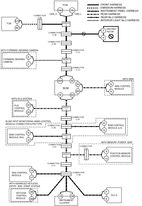
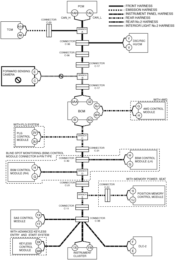
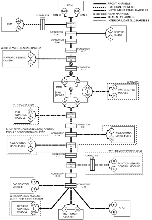
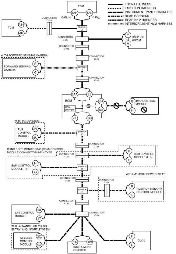
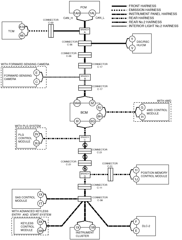
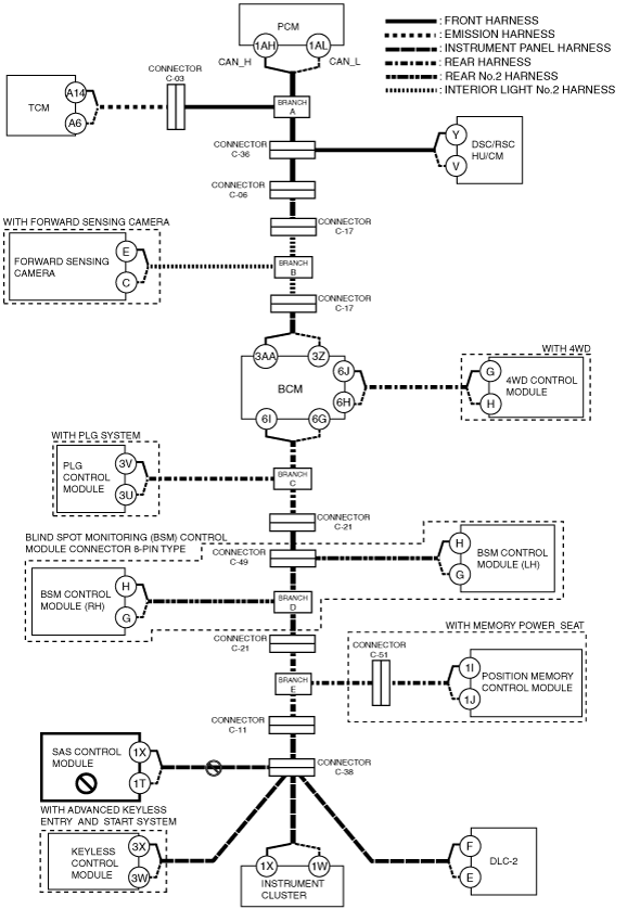
DETERMINING MALFUNCTIONING PART (HS-CAN) [MULTIPLEX COMMUNICATION SYSTEM (R.H.D.)]


id0902j4846700

Caution
•  If the malfunctioning part is detected in the communication line, before disconnecting the related connector for inspection, press the connector in the connection direction to verify that there is no looseness or disconnection.
•  When disconnecting the connector, verify that there is no damage, deformation, or corrosion of the connector terminals.

1.  Verify the CAN system-related module DTCs and the failed module using the (M-MDS).

2.  Look for a DTC display pattern and failed module display pattern in tandem which match.

Note
•  A hyphen “- “in the DTC output pattern table indicates that the DTC may be displayed depending on the malfunction detection conditions. If only an “דis indicated, it means the DTC will not be displayed.
•  If any of the following DTCs is displayed alone, perform the applicable DTC inspection. (See DTC TABLE [MULTIPLEX COMMUNICATION SYSTEM (L.H.D.)].)
―  TCM: U0415:00
―  Forward sensing camera: U0401:68, U0415:68, U0422:68, U0423:68, U2005:68
―  BCM: U0401
―  BSM control module (LH): U0401:68, U0402:68, U0422:68, U0534:68
―  BSM control module (RH): U0401:68, U0402:68, U0422:68, U0533:68
―  Position memory control module: U0431:68
―  Keyless control module: U2023
―  Instrument cluster: U2510

3.  Refer to the matching tandem diagnostic results (A to V) and inspect the possible cause and inspection item.

4.  Perform the DTC inspection after the repair procedure.

•  If any DTC is displayed, return to FOREWORD. (See FOREWORD [MULTIPLEX COMMUNICATION SYSTEM (R.H.D.)].)


Diagnostic Table for Determining Malfunctioning Part

Cross (×): Displayed
Hyphen (-): May or may not be displayed

M-MDS display

DTC display pattern

DTC output module

DTC

PCM
(PCM)
U0101:00
 
×


U0140:00


×


TCM
(TCM)
U0100:00
×


U0121:00


×


U0155:00


×
U0415:00


-


ABS
(DSC/RSC HU/CM)
U0100
×
 
×


U0140


×


U0155


×
FSC*1
(Forward sensing camera)
U0100:00
×
 
×
 
×


U0121:00


×
×


U0140:00


×


U0155:00


×
U0401:68
-
 
-
 
-


U0415:68


-
-


U0422:68


-


U0423:68


-
U2005:86
-
 
-
 
-


GEM
(BCM)
U0100
×
 
×
 
×
 
×


U0101
 
×
×
 
×
 
×


U0121


×
×
 
×


U0401
-
 
-
 
-
 
-


4×4*2
(4WD control module)
U0100
×
 
×
 
×
 
×


U0101
 
×
×
 
×
 
×


U0121


×
×
 
×


U0155


×
LTM*3
(PLG control module)
U0100
×
 
×
 
×
 
×
 
 
×


U0101
 
×
×
 
×
 
×
 
 
×


U0140


×
 
×


U0155


×
U0214


×
 
BSML*4
(BSM control module (LH))
U0100:00
×
 
×
 
×
 
×
 
 
×
 
×


U0101:00
 
×
×
 
×
 
×
 
 
×
 
×


U0140:00


×
 
×
 
×


U0233:00


×


U0401:68
-
 
-
 
-
 
-
 
 
-
 
-


U0402:68
 
-
-
 
-
 
-
 
 
-
 
-


U0422:68


-
 
-
 
-


U0534:68


-


BSML*4
(BSM control module (RH))
U0100:00
×
 
×
 
×
 
×
 
 
×
 
×
 
×


U0101:00
 
×
×
 
×
 
×
 
 
×
 
×
 
×


U0140:00


×
 
×
 
×
 
×


U0232:00


×
×


U0401:68
-
 
-
 
-
 
-
 
 
-
 
-
 
-


U0402:68
 
-
-
 
-
 
-
 
 
-
 
-
 
-


U0422:68


-
 
-
 
-
 
-


U0533:68


-
-


DSM*5
(Position memory control module)
U0100:00
×
 
×
 
×
 
×
 
 
×
 
×
 
×
 
×


U0101:00
 
×
×
 
×
 
×
 
 
×
 
×
 
×
 
×


U0121:00


×
×
 
×
 
 
×
 
×
 
×
 
×


U0140:00


×
 
×
 
×
 
×
 
×


U0155:00


×
U0431:68


-
 
-
 
-
 
-
 
-


RCM
(SAS control module)
U0155


×
RKE*6
(Keyless control module)
U0100
×
 
×
 
×
 
×
 
 
×
 
×
 
×
 
×
 
×


U0140


×
 
×
 
×
 
×
 
×
 
×


U0323


×
U2023
-
 
-
 
-
 
-
 
 
-
 
-
 
-
 
-
 
-


IC
(Instrument cluster)
U0100
×
 
×
 
×
 
×
 
 
×
 
×
 
×
 
×
 
×


U0101
 
×
×
 
×
 
×
 
 
×
 
×
 
×
 
×
 
×


U0114


×
×
 
×
 
×
 
×
 
×


U0121


×
×
 
×
 
 
×
 
×
 
×
 
×
 
×


U0140


×
 
×
 
×
 
×
 
×
 
×


U0151


×
 
 
U0200


×
×
 
×


U0214


×
 
U023A


×
×
 
 
×
 
×
 
×
 
×
 
×


U2510
-
 
-
 
-
 
-
 
 
-
 
-
 
-
 
-
 
-


M-MDS display module
“Fail” display pattern
PCM
×
 
×
 
×
 
×
 
 
×
 
×
 
×
 
×
 
×


TCM
 
×
×
 
×
 
×
 
 
×
 
×
 
×
 
×
 
×


ABS


×
×
 
×
 
 
×
 
×
 
×
 
×
 
×


FSC*1


×
×
 
 
×
 
×
 
×
 
×
 
×


GEM


×
 
×
 
×
 
×
 
×
 
×


4×4*2


×
×
 
×
 
×
 
×
 
×


LTM*3


×
×
 
×
 
×
 
×


BSML*4


×
×
 
×
 
×


BSMR*4


×
×
 
×


DSM*5


×
×


RCM


×
 
 
RKE*6


×
 
IC


×
Item
Diagnostic result
Possible cause and inspection item
A
B
C
D
E
F
G
H
I
J
K
L
M
N
O
P
Q
R
S
T
U
Reference page
A
B
C
D
E
F
G
H
I
J
K
L
M
N
O
P
Q
R
S
T
U

*1  :With Forward sensing camera
*2  :With 4WD
*3  :With PLG system
*4  :With blind spot monitoring (BSM) control module connector 8-pin type
*5  :With position memory control system
*6  :With advanced keyless entry and start system

A


Possible cause

•  Connector terminal disconnection, poor contact, damage, deformation, corrosion
•  PCM power supply voltage or body ground malfunction
•  Open circuit in wiring harness between PCM and branch A
•  PCM malfunction


System wiring diagram

ac9wzw00002697


Inspection item

•  PCM power supply voltage-related wiring harness and fuse
•  PCM body ground related wiring harness
•  PCM connector
•  Wiring harness between PCM terminal 1AH and branch A
•  Wiring harness between PCM terminal 1AL and branch A
•  PCM


B


Possible cause

•  Connector terminal disconnection, poor contact, damage, deformation, corrosion
•  TCM power supply voltage or body ground malfunction
•  Open circuit in wiring harness between TCM and connector C-03
•  Open circuit in wiring harness between connector C-03 and branch A
•  TCM malfunction
•  Connector C-03 malfunction


System wiring diagram

ac9wzw00002698


Inspection item

•  TCM power supply voltage-related wiring harness and fuse
•  TCM body ground related wiring harness
•  TCM connector
•  Connector C-03
•  Wiring harness between TCM terminal A14 and connector C-03
•  Wiring harness between TCM terminal A6 and connector C-03
•  Wiring harness between connector C-03 and branch A
•  TCM


C


Possible cause

•  Connector terminal disconnection, poor contact, damage, deformation, corrosion
•  Open circuit in wiring harness between branch A and connector C-36
•  Connector C-36 malfunction


System wiring diagram

ac9wzw00002699


Inspection item

•  Connector C-36
•  Wiring harness between branch A and connector C-36


D


Possible cause

•  Connector terminal disconnection, poor contact, damage, deformation, corrosion
•  DSC/RSC HU/CM power supply voltage or body ground malfunction
•  Open circuit in wiring harness DSC/RSC HU/CM and connector C-36
•  Connector C-36 malfunction
•  DSC/RSC HU/CM malfunction


System wiring diagram

ac9wzw00002700


Inspection item

•  DSC/RSC HU/CM power supply voltage-related wiring harness and fuse
•  DSC/RSC HU/CM body ground related wiring harness
•  DSC/RSC HU/CM connector
•  Connector C-36
•  Wiring harness between DSC/RSC HU/CM terminal Y and connector C-36
•  Wiring harness between DSC/RSC HU/CM terminal V and connector C-36
•  DSC/RSC HU/CM


E


With forward sensing camera

Possible cause
•  Connector terminal disconnection, poor contact, damage, deformation, corrosion
•  Open circuit in wiring harness connector C-36 and connector C-06
•  Open circuit in wiring harness connector C-06 and connector C-17
•  Open circuit in wiring harness connector C-17 and branch B
•  Connector C-36 malfunction
•  Connector C-06 malfunction
•  Connector C-17 malfunction

System wiring diagram

ac9wzw00002701
Inspection item
•  Connector C-36
•  Connector C-06
•  Connector C-17
•  Wiring harness between connector C-36 and connector C-06
•  Wiring harness between connector C-06 and connector C-17
•  Wiring harness between connector C-17 and branch B


Without forward sensing camera

Possible cause
•  Connector terminal disconnection, poor contact, damage, deformation, corrosion
•  Open circuit in wiring harness connector C-36 and connector C-06
•  Open circuit in wiring harness connector C-06 and connector C-17
•  Open circuit in wiring harness connector C-17 and connector C-17
•  Open circuit in wiring harness connector C-17 and BCM
•  Connector C-36 malfunction
•  Connector C-06 malfunction
•  Connector C-17 malfunction
•  BCM malfunction

System wiring diagram

ac9wzw00002702
Inspection item
•  BCM connector
•  Connector C-36
•  Connector C-06
•  Connector C-17
•  Wiring harness between connector C-36 and connector C-06
•  Wiring harness between connector C-06 and connector C-17
•  Wiring harness between connector C-17 and connector C-17
•  Wiring harness between BCM terminal 3AA and connector C-17
•  Wiring harness between BCM terminal 3Z and connector C-17
•  Inspect for continuity between the following terminals:
―  BCM terminal 3AA and terminal 6I
―  BCM terminal 3Z and terminal 6G


F


Possible cause

•  Connector terminal disconnection, poor contact, damage, deformation, corrosion
•  Forward sensing camera power supply voltage or body ground malfunction
•  Open circuit in wiring harness between forward sensing camera and branch B
•  Forward sensing camera malfunction


System wiring diagram

ac9wzw00002703


Inspection item

•  Forward sensing camera power supply voltage-related wiring harness and fuse
•  Forward sensing camera body ground related wiring harness
•  Forward sensing camera connector
•  Wiring harness between Forward sensing camera terminal E and branch B
•  Wiring harness between Forward sensing camera terminal C and branch B
•  Forward sensing camera


G


Possible cause

•  Connector terminal disconnection, poor contact, damage, deformation, corrosion
•  Open circuit in wiring harness between branch B and connector C-17
•  Open circuit in wiring harness between connector C-17 and BCM
•  Connector C-17 malfunction
•  BCM malfunction


System wiring diagram

ac9wzw00002704


Inspection item

•  BCM connector
•  Connector C-17
•  Wiring harness between branch B and connector C-17
•  Wiring harness between connector C-17 and BCM terminal 3AA
•  Wiring harness between connector C-17 and BCM terminal 3Z
•  Inspect for continuity between the following terminals:
―  BCM terminal 3AA and terminal 6I
―  BCM terminal 3Z and terminal 6G


H


Possible cause

•  Connector terminal disconnection, poor contact, damage, deformation, corrosion
•  BCM power supply voltage or body ground malfunction
•  BCM malfunction


System wiring diagram

ac9wzw00002706


Inspection item

•  BCM power supply voltage-related wiring harness and fuse
•  BCM body ground related wiring harness
•  BCM


I


Possible cause

•  Connector terminal disconnection, poor contact, damage, deformation, corrosion
•  4WD control module power supply voltage or body ground malfunction
•  Open circuit in wiring harness 4WD control module and BCM
•  BCM malfunction
•  4WD control module malfunction


System wiring diagram

ac9wzw00002705


Inspection item

•  4WD control module power supply voltage-related wiring harness and fuse
•  4WD control module body ground related wiring harness
•  BCM connector
•  4WD control module connector
•  Wiring harness between 4WD control module terminal G and BCM terminal 6J
•  Wiring harness between 4WD control module terminal H and BCM terminal 6H
•  Inspect for continuity between the following terminals:
―  BCM terminal 6J and terminal 3AA
―  BCM terminal 6H and terminal 3Z
•  4WD control module


J


With PLG system

Possible cause
•  Connector terminal disconnection, poor contact, damage, deformation, corrosion
•  Open circuit in wiring harness BCM and branch C
•  BCM malfunction

System wiring diagram

ac9wzw00002707
Inspection item
•  BCM connector
•  Wiring harness between BCM terminal 6I and branch B
•  Wiring harness between BCM terminal 6G and branch B
•  Inspect for continuity between the following terminals:
―  BCM terminal 3AA and terminal 6I
―  BCM terminal 3Z and terminal 6G


Without PLG system

Possible cause
•  Connector terminal disconnection, poor contact, damage, deformation, corrosion
•  Open circuit in wiring harness BCM and connector C-21
•  Open circuit in wiring harness connector C-21 and connector C-49
•  Connector C-21 malfunction
•  Connector C-49 malfunction

System wiring diagram

ac9wzw00002708
Inspection item
•  BCM connector
•  Connector C-21
•  Connector C-49
•  Wiring harness between BCM terminal 6I and connector C-21
•  Wiring harness between BCM terminal 6G and connector C-21
•  Wiring harness between connector C-21 and connector C-49
•  Inspect for continuity between the following terminals:
―  BCM terminal 3AA and terminal 6I
―  BCM terminal 3Z and terminal 6G


K


Possible cause

•  Connector terminal disconnection, poor contact, damage, deformation, corrosion
•  PLG control module power supply voltage or body ground malfunction
•  Open circuit in wiring harness PLG control module and branch C
•  PLG control module malfunction


System wiring diagram

ac9wzw00002709


Inspection item

•  PLG control module power supply voltage-related wiring harness and fuse
•  PLG control module body ground related wiring harness
•  PLG control module connector
•  Wiring harness between PLG control module terminal 3V and branch C
•  Wiring harness between PLG control module terminal 3U and branch C
•  PLG control module


L


With BSM system

Possible cause
•  Connector terminal disconnection, poor contact, damage, deformation, corrosion
•  Open circuit in wiring harness branch C and connector C-21
•  Open circuit in wiring harness connector C-21 and connector C-49
•  Connector C-21 malfunction
•  Connector C-49 malfunction

System wiring diagram

ac9wzw00002710
Inspection item
•  Connector C-21
•  Connector C-49
•  Wiring harness between branch C and connector C-21
•  Wiring harness between connector C-21 and connector C-49


Without BSM system

Possible cause
•  Connector terminal disconnection, poor contact, damage, deformation, corrosion
•  Open circuit in wiring harness branch C and connector C-21
•  Open circuit in wiring harness connector C-21 and connector C-21
•  Open circuit in wiring harness connector C-21 and branch D
•  Connector C-21 malfunction

System wiring diagram

ac9wzw00002711
Inspection item
•  Connector C-21
•  Wiring harness between branch C and connector C-21
•  Wiring harness between connector C-21 and connector C-21
•  Wiring harness between connector C-21 and branch D


M


Possible cause

•  Connector terminal disconnection, poor contact, damage, deformation, corrosion
•  BSM control module (LH) power supply voltage or body ground malfunction
•  Open circuit wiring harness BSM control module (LH) and connector C-49
•  Connector C-49 malfunction
•  BSM control module (LH) malfunction


System wiring diagram

ac9wzw00002712


Inspection item

•  BSM control module (LH) power supply voltage-related wiring harness and fuse
•  BSM control module (LH) body ground related wiring harness
•  BSM control module (LH) connector
•  Connector C-49
•  Wiring harness between BSM control module (LH) terminal H and connector C-49
•  Wiring harness between BSM control module (LH) terminal G and connector C-49
•  BSM control module (LH)


N


Possible cause

•  Connector terminal disconnection, poor contact, damage, deformation, corrosion
•  Open circuit in wiring harness between connector C-49 and branch D
•  Connector C-49 malfunction


System wiring diagram

ac9wzw00002713


Inspection item

•  Connector C-49
•  Wiring harness between connector C-49 and branch D


O


Possible cause

•  Connector terminal disconnection, poor contact, damage, deformation, corrosion
•  BSM control module (RH) power supply voltage or body ground malfunction
•  Open circuit in wiring harness between BSM control module (RH) and branch D
•  BSM control module (RH) malfunction


System wiring diagram

ac9wzw00002714


Inspection item

•  BSM control module (RH) power supply voltage-related wiring harness and fuse
•  BSM control module (RH) body ground related wiring harness
•  BSM control module (RH) connector
•  Wiring harness between BSM control module (RH) terminal H and branch D
•  Wiring harness between BSM control module (RH) terminal G and branch D
•  BSM control module (RH)


P


Possible cause

•  Connector terminal disconnection, poor contact, damage, deformation, corrosion
•  Open circuit in wiring harness between branch D and connector C-21
•  Open circuit in wiring harness between connector C-21 and branch E
•  Connector C-21 malfunction


System wiring diagram

ac9wzw00002715


Inspection item

•  Connector C-21
•  Wiring harness between branch D and connector C-21
•  Wiring harness between connector C-21 and branch E


Q


Possible cause

•  Connector terminal disconnection, poor contact, damage, deformation, corrosion
•  Position memory control module power supply voltage or body ground malfunction
•  Open circuit wiring harness branch E and connector C-51
•  Open circuit in wiring harness connector C-51 and position memory control module
•  Connector C-51 malfunction
•  Position memory control module malfunction


System wiring diagram

ac9wzw00002716


Inspection item

•  Position memory control module power supply voltage-related wiring harness and fuse
•  Position memory control module body ground related wiring harness
•  Connector C-51
•  Position memory control module connector
•  Wiring harness between blanch E and connector C-51
•  Wiring harness between position memory control module terminal 1I and connector C-51
•  Wiring harness between position memory control module terminal 1J and connector C-51
•  Position memory control module


R


Possible cause

•  Connector terminal disconnection, poor contact, damage, deformation, corrosion
•  Open circuit in wiring harness between branch E and connector C-11
•  Open circuit in wiring harness between connector C-11 and connector C-38
•  Connector C-11 malfunction
•  Connector C-38 malfunction


System wiring diagram

ac9wzw00002717


Inspection item

•  Connector C-11
•  Connector C-38
•  Wiring harness between branch E and connector C-11
•  Wiring harness between connector C-11 and connector C-38


S


Possible cause

•  Connector terminal disconnection, poor contact, damage, deformation, corrosion
•  SAS control module power supply voltage or body ground malfunction
•  Open circuit in wiring harness between SAS control module and connector C-38
•  Connector C-38 malfunction
•  SAS control module malfunction


System wiring diagram

ac9wzw00002718


Inspection item

•  SAS control module power supply voltage-related wiring harness and fuse
•  SAS control module body ground related wiring harness
•  SAS control module connector
•  Connector C-38
•  Wiring harness between SAS control module terminal 1X and connector C-38
•  Wiring harness between SAS control module terminal 1T and connector C-38
•  SAS control module


T


Possible cause

•  Connector terminal disconnection, poor contact, damage, deformation, corrosion
•  Keyless control module power supply voltage or body ground malfunction
•  Open circuit in wiring harness between keyless control module and connector C-38
•  Connector C-38 malfunction
•  Keyless control module malfunction


System wiring diagram

ac9wzw00002720


Inspection item

•  Keyless control module power supply voltage-related wiring harness and fuse
•  Keyless control module body ground related wiring harness
•  Keyless control module connector
•  Connector C-38
•  Wiring harness between keyless control module terminal 3X and connector C-38
•  Wiring harness between keyless control module terminal 3W and connector C-38
•  Keyless control module


U


Possible cause

•  Connector terminal disconnection, poor contact, damage, deformation, corrosion
•  Instrument cluster power supply voltage or body ground malfunction
•  Open circuit in wiring harness between connector C-38 and Instrument cluster
•  Connector C-38 malfunction
•  Instrument cluster malfunction


System wiring diagram

ac9wzw00002721


Inspection item

•  Instrument cluster power supply voltage-related wiring harness and fuse
•  Instrument cluster body ground related wiring harness
•  Instrument cluster connector
•  Connector C-38
•  Wiring harness between instrument cluster terminal 1X and connector C-38
•  Wiring harness between instrument cluster terminal 1W and connector C-38
•  Instrument cluster