DETERMINING MALFUNCTIONING PART (MS-CAN) [MULTIPLEX COMMUNICATION SYSTEM (R.H.D.)]
id0902j4846800
-
Caution
-
• If the malfunctioning part is detected in the communication line, before disconnecting the related connector for inspection, press the connector in the connection direction to verify that there is no looseness or disconnection.
• When disconnecting the connector, verify that there is no damage, deformation, or corrosion of the connector terminals.
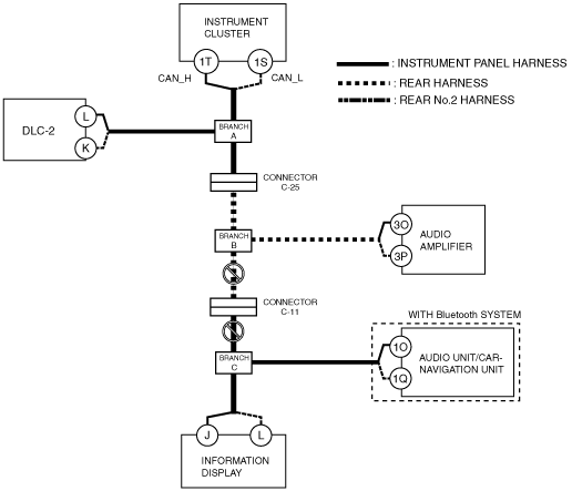
Type A (Blind Spot Monitoring (BSM) Control Module Connector 8-pin Type)
1. Verify DTCs of the modules related to the CAN system.
2. Apply the following items to the DTC Output Pattern and Malfunctioning Part, and then verify the reference to the malfunctioning location. (See DTC Output Pattern and Malfunctioning Part.)
-
• Communication error DTCs
• Malfunctioning module
-
Note
-
• A hyphen(-) in the DTC output pattern cell indicates that the DTC may be displayed depending on the malfunction detection conditions. If it is not displayed, the malfunctioning part can be determined by checking only the crosses (×).
3. Inspect the possible cause and inspection item of the applicable malfunctioning part.
4. Perform the DTC inspection after the repair procedure.
-
DTC Output Pattern and Malfunctioning Part
Cross (×): Displayed
Hyphen (-): May or may not be displayed
|
DTC display
|
DTC display pattern
|
|
DTC output module
|
DTC
|
A
|
B
|
C
|
D
|
E
|
F
|
G
|
H
|
|
Information display*6
|
02:1E*1
|
|
|
|
|
|
×
|
×
|
×
|
|
02:3E*1
|
×
|
×
|
×
|
|
×
|
|
|
×
|
|
Information display*7
|
02 1E*1
|
|
|
|
|
|
×
|
×
|
×
|
|
02 3E*1
|
×
|
×
|
×
|
|
×
|
|
|
×
|
|
M-MDS display module
|
“Fail” display pattern
|
|
IC*3
|
×
|
|
|
|
|
|
|
|
|
AM*4
|
|
|
×
|
×
|
|
|
|
|
|
ACU*5
|
|
|
×
|
|
×
|
×
|
|
|
|
Information display
|
Display pattern on information display
|
|
02:1-*2
|
|
|
-
|
|
-
|
-
|
-
|
-
|
*1 :The DTC is displayed on the information display.
*2 :If "02:1-" is displayed on the information display, no DTC is displayed.
*3 :Instrument cluster
*4 :Audio amplifier
*5 :Audio unit
*6 :With clock display
*7 :Without clock display
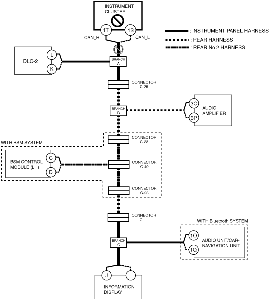
A
-
Possible cause
-
• Connector terminal disconnection, poor contact, damage, deformation, corrosion
• Instrument cluster power supply voltage or body ground malfunction
• Open circuit in wiring harness between instrument cluster and branch A
• Instrument cluster malfunction
System wiring diagram
-
Inspection item
-
• Instrument cluster power supply voltage-related wiring harness and fuse
• Instrument cluster body ground related wiring harness
• Instrument cluster connector
• Wiring harness between instrument cluster terminal 1T and branch A
• Wiring harness between instrument cluster terminal 1S and branch A
• Instrument cluster
B
-
Possible cause
-
• Connector terminal disconnection, poor contact, damage, deformation, corrosion
• Instrument cluster power supply voltage or body ground malfunction
• Open circuit in wiring harness between Instrument cluster and branch A
• Instrument cluster malfunction
System wiring diagram
-
• Instrument cluster power supply voltage-related wiring harness and fuse
• Instrument cluster body ground related wiring harness
• Instrument cluster connector
• Wiring harness between instrument cluster terminal 1T and branch A
• Wiring harness between instrument cluster terminal 1S and branch A
• Instrument cluster
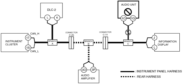
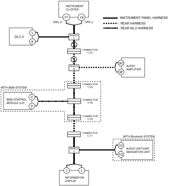
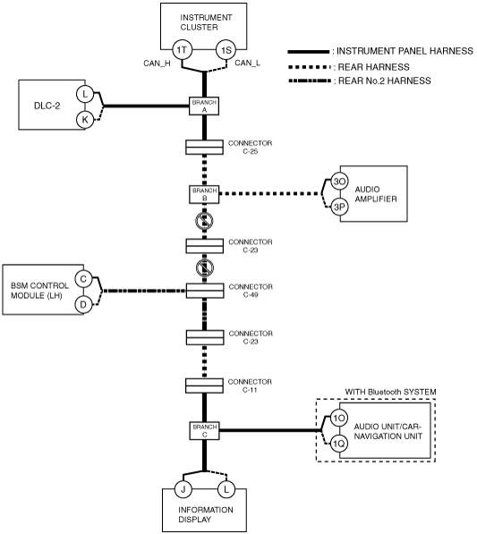
C
-
Possible cause
-
• Connector terminal disconnection, poor contact, damage, deformation, corrosion
• Open circuit in wiring harness between branch A and connector C-25
• Open circuit in wiring harness between connector C-25 and branch B
• Connector C-25 malfunction
System wiring diagram
-
Inspection item
-
• Connector C-25
• Wiring harness between branch A and connector C-25
• Wiring harness between connector C-25 and branch B
D
-
• Connector terminal disconnection, poor contact, damage, deformation, corrosion
• Audio amplifier power supply voltage or body ground malfunction
• Open circuit in wiring harness between audio amplifier and branch B
• Audio amplifier malfunction
System wiring diagram
-
Inspection item
-
• Audio amplifier power supply voltage-related wiring harness and fuse
• Audio amplifier body ground related wiring harness
• Audio amplifier connector
• Wiring harness between audio amplifier terminal 3O and branch B
• Wiring harness between audio amplifier terminal 3P and branch B
• Audio amplifier
E
-
Possible cause
-
• Connector terminal disconnection, poor contact, damage, deformation, corrosion
• Open circuit in wiring harness between branch B and connector C-11
• Open circuit in wiring harness between connector C-11 and branch C
• Connector C-11 malfunction
System wiring diagram
-
Inspection item
-
• Connector C-11
• Wiring harness between branch B and connector C-11
• Wiring harness between connector C-11 and branch C
F
-
Possible cause
-
• Connector terminal disconnection, poor contact, damage, deformation, corrosion
• Audio unit power supply voltage or body ground malfunction
• Open circuit in wiring harness between audio unit and branch C
• Audio unit malfunction
System wiring diagram
-
Inspection item
-
• Audio unit power supply voltage-related wiring harness and fuse
• Audio unit body ground related wiring harness
• Audio unit connector
• Wiring harness between audio unit terminal 1O and branch C
• Wiring harness between audio unit terminal 1Q and branch C
• Audio unit
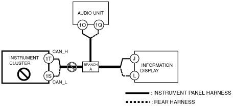
G
-
Possible cause
-
• Connector terminal disconnection, poor contact, damage, deformation, corrosion
• Audio unit power supply voltage or body ground malfunction
• Open circuit in wiring harness between audio unit and branch A
• Audio unit malfunction
System wiring diagram
-
Inspection item
-
• Audio unit power supply voltage-related wiring harness and fuse
• Audio unit body ground related wiring harness
• Audio unit connector
• Wiring harness between audio unit terminal 1O and branch A
• Wiring harness between audio unit terminal 1Q and branch A
• Audio unit
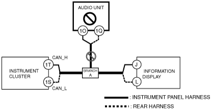
H
-
With Bose®
Possible cause
-
• Connector terminal disconnection, poor contact, damage, deformation, corrosion
• Information display power supply voltage or body ground malfunction
• Open circuit in wiring harness between branch C and information display
• Information display malfunction
System wiring diagram
-
Inspection item
-
• Information display power supply voltage-related wiring harness and fuse
• Information display body ground related wiring harness
• Information display connector
• Wiring harness between branch C and information display
• Information display
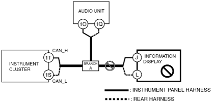
-
Without Bose®
Possible cause
-
• Connector terminal disconnection, poor contact, damage, deformation, corrosion
• Information display power supply voltage or body ground malfunction
• Open circuit in wiring harness between branch A and information display
• Information display malfunction
System wiring diagram
-
Inspection item
-
• Information display power supply voltage-related wiring harness and fuse
• Information display body ground related wiring harness
• Information display connector
• Wiring harness between branch A and information display
• Information display
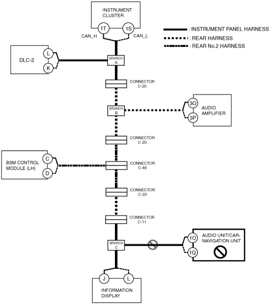
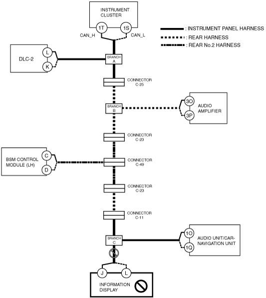
Type B (Blind Spot Monitoring (BSM) Control Module Connector 10-pin Type)
1. Verify DTCs of the modules related to the CAN system.
2. Apply the following items to the DTC Output Pattern and Malfunctioning Part, and then verify the reference to the malfunctioning location. (See DTC Output Pattern and Malfunctioning Part.)
-
• Communication error DTCs
• Malfunctioning module
-
Note
-
• A hyphen(-) in the DTC output pattern cell indicates that the DTC may be displayed depending on the malfunction detection conditions. If it is not displayed, the malfunctioning part can be determined by checking only the crosses (×).
3. Inspect the possible cause and inspection item of the applicable malfunctioning part.
4. Perform the DTC inspection after the repair procedure.
-
DTC Output Pattern and Malfunctioning Part
Cross (×): Displayed
Hyphen (-): May or may not be displayed
|
DTC display
|
DTC display pattern
|
|
DTC output module
|
DTC
|
I
|
J
|
K
|
L
|
M
|
N
|
O
|
P
|
|
IC
(Instrument cluster)
|
U0200
|
|
×
|
|
×
|
×
|
|
|
|
|
BSML
(BSM control module (LH))
|
U0100:00
|
×
|
|
|
|
|
|
|
|
|
U0140:00
|
×
|
|
|
|
|
|
|
|
|
Information display*7
|
02:1E*1
|
|
|
|
|
|
|
×
|
×
|
|
02:3E*1
|
×
|
×
|
|
×
|
|
×
|
|
×
|
|
Information display*8
|
02 1E*1
|
|
|
|
|
|
|
×
|
×
|
|
02 3E*1
|
×
|
×
|
|
×
|
|
×
|
|
×
|
|
M-MDS display module
|
“Fail” display pattern
|
|
IC*3
|
×
|
|
|
|
|
|
|
|
|
AM*4
|
|
×
|
×
|
|
|
|
|
|
|
BSML*5
|
|
×
|
|
×
|
×
|
|
|
|
|
ACU*6
|
|
×
|
|
×
|
|
×
|
×
|
|
|
Information display
|
Display pattern on information display
|
|
02:1-*2
|
|
|
|
|
|
|
-
|
-
|
*1 :The DTC is displayed on the information display.
*2 :If "02:1-" is displayed on the information display, no DTC is displayed.
*3 :Instrument cluster
*4 :Audio amplifier
*5 :BSM control module (LH)
*6 :Audio unit
*7 :With clock display
*8 :Without clock display
I
-
Possible cause
-
• Connector terminal disconnection, poor contact, damage, deformation, corrosion
• Instrument cluster power supply voltage or body ground malfunction
• Open circuit in wiring harness between instrument cluster and branch A
• Instrument cluster malfunction
System wiring diagram
-
Inspection item
-
• Instrument cluster power supply voltage-related wiring harness and fuse
• Instrument cluster body ground related wiring harness
• Instrument cluster connector
• Wiring harness between instrument cluster terminal 1T and branch A
• Wiring harness between instrument cluster terminal 1S and branch A
• Instrument cluster
J
-
Possible cause
-
• Connector terminal disconnection, poor contact, damage, deformation, corrosion
• Open circuit in wiring harness between branch A and connector C-25
• Open circuit in wiring harness between connector C-25 and branch B
• Connector C-25 malfunction
System wiring diagram
-
Inspection item
-
• Connector C-25
• Wiring harness between branch A and connector C-25
• Wiring harness between connector C-25 and branch B
K
-
• Connector terminal disconnection, poor contact, damage, deformation, corrosion
• Audio amplifier power supply voltage or body ground malfunction
• Open circuit in wiring harness between audio amplifier and branch B
• Audio amplifier malfunction
System wiring diagram
-
Inspection item
-
• Audio amplifier power supply voltage-related wiring harness and fuse
• Audio amplifier body ground related wiring harness
• Audio amplifier connector
• Wiring harness between audio amplifier terminal 3O and branch B
• Wiring harness between audio amplifier terminal 3P and branch B
• Audio amplifier
L
-
With BSM system
Possible cause
-
• Connector terminal disconnection, poor contact, damage, deformation, corrosion
• Open circuit in wiring harness between branch B and connector C-23
• Open circuit in wiring harness between connector C-23 and connector C-49
• Connector C-23 malfunction
• Connector C-49 malfunction
System wiring diagram
-
Inspection item
-
• Connector C-23
• Connector C-49
• Wiring harness between branch B and connector C-23
• Wiring harness between connector C-23 and connector C-49
-
Without BSM system
Possible cause
-
• Connector terminal disconnection, poor contact, damage, deformation, corrosion
• Open circuit in wiring harness between branch B and connector C-11
• Open circuit in wiring harness between connector C-11 and branch C
• Connector C-11 malfunction
-
Inspection item
-
• Connector C-11
• Wiring harness between branch B and connector C-11
• Wiring harness between connector C-11 and branch C
M
-
Possible cause
-
• Connector terminal disconnection, poor contact, damage, deformation, corrosion
• BSM control module (LH) power supply voltage or body ground malfunction
• Open circuit in wiring harness between BSM control module (LH) and connector C-49
• Connector C-49 malfunction
• BSM control module (LH) malfunction
System wiring diagram
-
Inspection item
-
• BSM control module (LH) power supply voltage-related wiring harness and fuse
• BSM control module (LH) body ground related wiring harness
• Connector C-49
• BSM control module (LH) connector
• Wiring harness between BSM control module (LH) terminal C and connector C-49
• Wiring harness between BSM control module (LH) terminal D and connector C-49
• BSM control module (LH)
N
-
Possible cause
-
• Connector terminal disconnection, poor contact, damage, deformation, corrosion
• Open circuit in wiring harness between connector C-49 and connector C-23
• Open circuit in wiring harness between connector C-23 and connector C-11
• Open circuit in wiring harness between connector C-11 and branch C
• Connector C-49 malfunction
• Connector C-23 malfunction
• Connector C-11 malfunction
System wiring diagram
-
Inspection item
-
• Connector C-49
• Connector C-23
• Connector C-11
• Wiring harness between connector C-49 and connector C-23
• Wiring harness between connector C-23 and connector C-11
• Wiring harness between connector C-11 and branch C
O
-
Possible cause
-
• Connector terminal disconnection, poor contact, damage, deformation, corrosion
• Audio unit/car-navigation unit power supply voltage or body ground malfunction
• Open circuit in wiring harness between audio unit/car-navigation unit and branch C
• Audio unit/car-navigation unit malfunction
System wiring diagram
-
Inspection item
-
• Audio unit/car-navigation unit power supply voltage-related wiring harness and fuse
• Audio unit/car-navigation unit body ground related wiring harness
• Audio unit/car-navigation unit connector
• Wiring harness between audio unit/car-navigation unit terminal 1O and branch C
• Wiring harness between audio unit/car-navigation unit terminal 1Q and branch C
• Audio unit/car-navigation unit
P
-
Possible cause
-
• Connector terminal disconnection, poor contact, damage, deformation, corrosion
• Information display power supply voltage or body ground malfunction
• Open circuit in wiring harness between Information display and branch C
• Information display malfunction
System wiring diagram
-
Inspection item
-
• Information display power supply voltage-related wiring harness and fuse
• Information display body ground related wiring harness
• Information display connector
• Wiring harness between Information display terminal J and branch C
• Wiring harness between Information display terminal L and branch C
• Information display