|
1
|
CLASSIFY OPEN CIRCUIT OR SHORT TO POWER SUPPLY MALFUNCTION
• Start the engine and run it at idle.
• Verify the BSM indicator light (RH) status.
• Does the BSM indicator light (RH) always illuminate?
|
Yes
|
Go to the next step.
|
|
No
|
Go to Step 7.
|
|
2
|
INSPECT POWER OUTER MIRROR (RH) CONNECTOR
• Turn the ignition switch to the OFF position.
• Disconnect the negative battery cable.
• Disconnect the power outer mirror (RH) connector.
• Inspect the connector engagement and connection condition and inspect the terminals for damage, deformation, corrosion, or disconnection.
• Is there any malfunction?
|
Yes
|
Repair or replace the connector, then go to Step 13.
|
|
No
|
Go to the next step.
|
|
3
|
INSPECT BSM CONTROL MODULE (RH) CONNECTOR
• Disconnect the BSM control module (RH) connector.
• Inspect the connector engagement and connection condition and inspect the terminals for damage, deformation, corrosion, or disconnection.
• Is there any malfunction?
|
Yes
|
Repair or replace the connector, then go to Step 13.
|
|
No
|
Go to the next step.
|
|
4
|
INSPECT BSM INDICATOR LIGHT (RH) SIGNAL CIRCUIT FOR SHORT TO POWER SUPPLY
• Verify that the power outer mirror (RH) and BSM control module (RH) connectors are disconnected.
• Reconnect the negative battery cable.
• Start the engine and run it at idle.
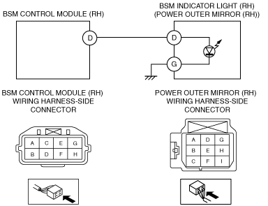
• Measure the voltage at the power outer mirror (RH) terminal D (wiring harness-side).
• Is the voltage 0 V?
|
Yes
|
Go to the next step.
|
|
No
|
Repair or replace the wiring harness which has a short to power supply, then go to Step 13.
|
|
5
|
INSPECT POWER OUTER MIRROR (RH)
• Inspect the power outer mirror (RH).
• Is there any malfunction?
|
Yes
|
Replace the power outer mirror (RH), then go to Step 13.
|
|
No
|
Go to the next step.
|
|
6
|
INSPECT BSM INDICATOR LIGHT (RH)
• Inspect the BSM indicator light (RH).
• Is there any malfunction?
|
Yes
|
Replace the outer mirror glass (RH), then go to Step 13.
|
|
No
|
Go to Step 13.
|
|
7
|
INSPECT POWER OUTER MIRROR (RH) CONNECTOR
• Turn the ignition switch to the OFF position.
• Disconnect the negative battery cable.
• Disconnect the power outer mirror (RH) connector.
• Inspect the connector engagement and connection condition and inspect the terminals for damage, deformation, corrosion, or disconnection.
• Is there any malfunction?
|
Yes
|
Repair or replace the connector, then go to Step 13.
|
|
No
|
Go to the next step.
|
|
8
|
INSPECT BSM INDICATOR LIGHT (RH) GROUND CIRCUIT FOR OPEN CIRCUIT
• Verify that the power outer mirror (RH) connector is disconnected.
• Inspect for continuity between power outer mirror (RH) terminal G (wiring harness-side) and body ground.
• Is there continuity?
|
Yes
|
Go to the next step.
|
|
No
|
Repair or replace the wiring harness which has an open circuit, then go to Step 13.
|
|
9
|
INSPECT POWER OUTER MIRROR (RH)
• Inspect the power outer mirror (RH).
• Is there any malfunction?
|
Yes
|
Replace the power outer mirror (RH), then go to Step 13.
|
|
No
|
Go to the next step.
|
|
10
|
INSPECT BSM INDICATOR LIGHT (RH)
• Inspect the BSM indicator light (RH).
• Is there any malfunction?
|
Yes
|
Replace the outer mirror glass (RH), then go to Step 13.
|
|
No
|
Go to the next step.
|
|
11
|
INSPECT BSM CONTROL MODULE (RH) CONNECTOR
• Disconnect the BSM control module (RH) connector.
• Inspect the connector engagement and connection condition and inspect the terminals for damage, deformation, corrosion, or disconnection.
• Is there any malfunction?
|
Yes
|
Repair or replace the connector, then go to Step 13.
|
|
No
|
Go to the next step.
|
|
12
|
INSPECT BSM INDICATOR LIGHT (RH) SIGNAL CIRCUIT FOR OPEN CIRCUIT
• Verify that the power outer mirror (RH) and BSM control module (RH) connectors are disconnected.
• Inspect for continuity between power outer mirror (RH) terminal D (wiring harness-side) and BSM control module (RH) terminal D (wiring harness-side).
• Is there continuity?
|
Yes
|
Go to the next step.
|
|
No
|
Repair or replace the wiring harness which has an open circuit, then go to the next step.
|
|
13
|
VERIFY DTC TROUBLESHOOTING COMPLETED
• Make sure to reconnect all disconnected connectors.
• Reconnect the negative battery cable.
• Clear the DTC for the BSM control module (RH) using the M-MDS.
• Retrieve the BSM control module (RH) DTCs using the M-MDS.
• Is the same DTC displayed?
|
Yes
|
Repeat the inspection from Step 1.
• If the malfunction recurs, replace the BSM control module (RH).
Go to the next step.
|
|
No
|
Go to the next step.
|
|
14
|
VERIFY IF OTHER DTCs DISPLAYED
• Are any other DTCs displayed?
|
Yes
|
Repair or replace the malfunctioning part according to the applicable DTC troubleshooting.
|
|
No
|
DTC troubleshooting completed.
|