|
1
|
INSPECT FOR MALFUNCTION IN BCM POWER SUPPLY CIRCUIT OR ELSEWHERE
• Did any of the following items operate during the KEYLESS ENTRY SYSTEM OPERATION INSPECTION?
-
― All doors lock/unlock
― Hazard wiring light flashes
|
Yes
|
Go to the next step.
|
|
No
|
Inspect the connection of the BCM connectors, and go to Step 4.
|
|
2
|
INSPECT FOR MALFUNCTION IN KEYLESS SWITCH OR ELSEWHERE
• Did the following item operate during the KEYLESS ENTRY SYSTEM OPERATION INSPECTION?
-
― All doors lock/unlock
|
Yes
|
Go to the next step.
|
|
No
|
Go to Step 7.
|
|
3
|
INSPECT FOR MALFUNCTION IN DOOR LOCK ACTUATOR OR ELSEWHERE
• Did the following item operate during the KEYLESS ENTRY SYSTEM OPERATION INSPECTION?
-
― Hazard warning light flashes
|
Yes
|
Go to the next step.
|
|
No
|
Go to Step 8.
|
|
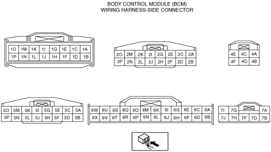
*4
|
INSPECT BCM POWER SUPPLY CIRCUIT
• Are the BCM power supply and voltage normal?
-
― IG1 signal (terminal 4A)
― B+ signal (terminal 2B, 2P)
|
Yes
|
Go to the next step.
|
|
No
|
• Inspect for burnt fuse.
• Inspect the power supply system wiring harness for an open or short circuit.
|
|
*5
|
INSPECT BCM GROUND CIRCUIT
• Is the BCM ground voltage normal?
-
― 0V (terminal 2G, 2N)
|
Yes
|
Go to the next step.
|
|
No
|
Inspect the ground system wiring harness for open circuit.
|
|
*6
|
INSPECT DOOR SWITCH SIGNAL VOLTAGE
• Are the wiring harness between the BCM and each door switch normal?
-
― Inspect each terminal (6M, 6O, 6R, 6Q) under the following conditions.
• Door closed: B+
• Door open: 2.0V or less
|
Yes
|
Go to the next step.
|
|
No
|
• Inspect the door switch.
• Inspect the door switch system wiring harness for a short circuit.
|
|
7
|
INSPECT KEYLESS SWITCH
• Is the keyless switch normal?
|
Yes
|
Replace the BCM.
|
|
No
|
Replace the keyless switch.
|
|
*8
|
INSPECT IF MALFUNCTION IS IN DOOR LOCK ACTUATOR, BCM GROUND CIRCUIT OR ELSEWHERE
• Measure the voltage at the BCM terminals 5I, 2H, 7D, 5E, 2L and 7G while operating the transmitter.
-
― Lock driver-side door with the transmitter: 1.0 V or less → B+→ 1.0 V or less (terminal 5I)
― Lock passenger-side door with the transmitter: 1.0 V or less → B+→ 1.0 V or less (terminal 2H)
― Lock all rear doors and liftgate with the transmitter: 1.0 V or less → B+→ 1.0 V or less (terminal 7D)
― Unlock driver-side door with the transmitter: 1.0 V or less → B+→ 1.0 V or less (terminal 5E)
― Unlock passenger-side door with the transmitter: 1.0 V or less → B+→ 1.0 V or less (terminal 2L)
― Unlock all rear doors and liftgate with the transmitter: 1.0 V or less → B+→ 1.0 V or less (terminal 7G)
• Is the voltage as above?
|
Yes
|
Go to the next step.
|
|
No
|
• Inspect the wiring harness between BCM and the door lock actuator for an open or short circuit.
• Inspect the door lock actuator.
|
|
9
|
INSPECT DOOR LOCK LINKAGE
• Operate the door lock knob and verify the door locks and unlock manually.
• Does every door lock system work?
|
Yes
|
Go to the next step.
|
|
No
|
Inspect the door lock linkage.
|
|
*10
|
INSPECT TURN LIGHT SIGNAL CIRCUIT
• Measure voltage at the BCM terminals 1I, 6A, 1G (right side turn signal), 3Y, 6C and 1F (left side turn signal) while operating hazard and/or turn signal on.
• Are the terminal voltages are alternated between 1.0V or less and B+?
|
Yes
|
Verify the malfunction symptom again.
|
|
No
|
• Inspect the wiring harnesses between the BCM and each turn light for a short circuit.
• Inspect each turn light.
• If these items are normal, replace the BCM.
|