 |
ac9uuw00000855
POWER LIFTGATE (PLG) CONTROL MODULE INSPECTION
id091100001000
1. Measure the PLG control module terminal voltage.
2. If there is large difference between the measured value and the value in the terminal voltage table, inspect the parts under “Inspection item(s)” and related wiring harnesses.
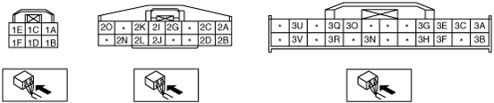
Terminal Voltage Table (Reference)
ac9uuw00000855
|
|
Terminal |
Signal name |
Connected to |
Measurement condition |
Voltage (V)/Continuity |
Inspection item(s) |
|---|---|---|---|---|---|
|
1A
|
Closure motor (Closed)
|
Closure motor
|
After opening the liftgate, operate the closure motor with the liftgate half-closed
|
0 → B+→ 0
|
• Liftgate latch and lock actuator
|
|
1B
|
Closure motor (Open)
|
Closure motor
|
Open the fully closed liftgate by hand
|
0 → B+→ 0
|
• Liftgate latch and lock actuator
• Liftgate outer handle switch
|
|
1C
|
Power supply
|
P.LIFT GATE 20 A fuse
|
Under any condition
|
B+
|
P.LIFT GATE 20 A fuse
|
|
1D
|
GND
|
Body ground
|
Under any condition
|
1.0 or less
|
• Related wiring harnesses
|
|
1E
|
PLG motor (Open)
|
PLG motor
|
Open the fully closed liftgate
|
0 → B+→ 0
|
PLG drive unit
|
|
1F
|
PLG motor (Closed)
|
PLG motor
|
Close the fully opened liftgate
|
0 → B+→ 0
|
PLG drive unit
|
|
2A
|
IG1
|
METER-B 7.5 A fuse
|
Ignition switch is at ON position
|
B+
|
METER-B 7.5 A fuse
|
|
Ignition switch is at OFF or ACC position
|
1.0 or less
|
||||
|
2B
|
PLG rear switch signal
|
PLG rear switch
|
When operating the PLG rear switch
|
B+
|
PLG rear switch
|
|
When not operating the PLG rear switch
|
1.0 or less
|
||||
|
2C
|
PLG buzzer output
|
PLG buzzer
|
When the PLG buzzer is sounding
|
B+
|
PLG buzzer
|
|
Other
|
1.0 or less
|
||||
|
2D
|
PLG touch sensor GND
|
Body ground
|
Under any condition
|
1.0 or less
|
• Related wiring harnesses
|
|
2G
|
Clutch output (-)
|
PLG clutch
|
When PLG is open or closing
|
1.0 or less
|
PLG drive unit
|
|
Other
|
No Continuity
|
||||
|
2I
|
Clutch output (+)
|
PLG clutch
|
When PLG is open or closing
|
B+
|
PLG drive unit
|
|
Other
|
1.0 or less
|
||||
|
2J
|
PLG motor rotation signal A
|
Rotation sensor
|
Pulse signal
|
-
|
PLG drive unit
|
|
2K
|
Rotation signal power source
|
Rotation sensor
|
Under any condition
|
5
|
PLG drive unit
|
|
2L
|
PLG motor rotation signal B
|
Rotation sensor
|
Pulse signal
|
-
|
PLG drive unit
|
|
2N
|
Rotation sensor GND
|
Body ground
|
Under any condition
|
1.0 or less
|
• Related wiring harnesses
|
|
2O
|
Power supply
|
BCM
|
Under any condition
|
B+
|
BCM
|
|
3A
|
PLG touch sensor signal (RH)
|
PLG touch sensor (RH)
|
When sensor is operating normally (usually)
|
0.5—4.2 or less
|
PLG touch sensor (RH)
|
|
When sensor is at fault
|
Other than those above
|
||||
|
3B
|
PLG touch sensor signal (LH)
|
PLG touch sensor (LH)
|
When sensor is operating normally (usually)
|
0.5—4.2 or less
|
PLG touch sensor (LH)
|
|
When sensor is at fault
|
Other than those above
|
||||
|
3C
|
Lock signal
|
Passenger seat side lock link switch
|
Passenger-side door locked
|
1.0 or less
|
Passenger seat side lock link switch
|
|
Passenger-side door unlocked
|
Wave pattern (See Pattern 1.)
|
||||
|
3E
|
Motor return signal
|
Return switch
|
After opening the liftgate, operate the closure motor with the liftgate half-closed
|
1.0 or less
|
• Liftgate latch and lock actuator
|
|
3F
|
Liftgate latch switch signal
|
Liftgate latch switch
|
Liftgate is open (liftgate latch switch is ON)
|
1.0 or less
|
Liftgate latch and lock actuator
|
|
Liftgate is closed (liftgate latch switch is OFF)
|
B+
|
||||
|
3G
|
Full latch switch
|
Latch position switch
|
After opening the liftgate, operate the closure motor with the liftgate half-closed
|
1.0 or less→ B+→ 1.0 or less
|
• Liftgate latch and lock actuator
|
|
3H
|
Half latch switch
|
Latch position switch
|
After opening the liftgate, operate the closure motor with the liftgate half-closed
|
1.0 or less→ B+
|
• Liftgate latch and lock actuator
|
|
3N*1
|
Unlock signal
|
Passenger seat side lock link switch
|
Passenger-side door locked
|
Wave pattern (See Pattern 2.)
|
Passenger seat side lock link switch
|
|
Passenger-side door unlocked
|
1.0 or less
|
||||
|
3O
|
Liftgate outer handle switch signal
|
Liftgate outer handle switch
|
When operating the liftgate outer handle (When the liftgate outer handle switch is ON)
|
B+
|
Liftgate outer handle switch
|
|
When not operating the liftgate outer handle (When the liftgate outer handle switch is OFF)
|
1.0 or less
|
||||
|
3Q
|
PLG front switch signal (Input)
|
PLG front switch
|
PLG front switch: Switch is at ON
|
B+
|
PLG front switch
|
|
PLG front switch: Switch is at OFF
|
1.0 or less
|
||||
|
3R
|
Power supply to PLG switches
|
PLG switch
|
PLG front switch: Open or close switch is at ON
|
1.0 or less
|
PLG control module
|
|
PLG front switch: Open or close switch is at OFF
|
B+
|
||||
|
3U
|
CAN_L
|
-
|
Because this terminal is for communication, good/no good judgment by terminal voltage is not possible
|
-
|
|
|
3V
|
CAN_H
|
-
|
Because this terminal is for communication, good/no good judgment by terminal voltage is not possible
|
-
|
|
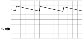
Generated pulse (reference)
Pattern 1
ac9uuw00003072
|
Pattern 2
ac9wzw00001203
|