 |
ac9wzw00002873
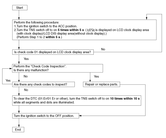
INFORMATION DISPLAY INPUT/OUTPUT CHECK MODE
id092200801300
Check Code Table
|
Check code |
Check item |
Related items |
|---|---|---|
|
01
|
Information display
|
CAN system
• 01:Er/01 Er :CAN system communication error
|
|
02
|
• Audio unit
• Instrument cluster
|
CAN system
• 02:1E/02 1E :Communication error to audio unit
• 02:3E/02 3E :Communication error to instrument cluster
|
|
04
|
TNS relay
|
• TNS relay
• TNS signal wiring harness
|
|
06
|
Ignition switch
|
Ignition switch
|
|
—
|
LCD
|
LCD
|
ac9wzw00002873
|
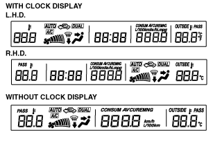
Check Code Inspection
Check code 01
|
Check code 01 |
CAN system |
||
|---|---|---|---|
|
INSPECTION CONDITION |
DISPLAY |
ACTION |
|
|
With clock display |
Without clock display |
||
|
Select the check code 01.
|
 |
 |
CAN system of information display is normal.
|
 |
 |
CAN system communication error.
|
|
Check code 02
|
Check code 02 |
• Communication status to audio unit
• Communication status to instrument cluster
|
|||
|---|---|---|---|---|
|
INSPECTION CONDITION |
DISPLAY |
ACTION |
||
|
Unit |
With clock display |
Without clock display |
||
|
Select the check code 02.
(The diagnostic results will be displayed once each in the order of audio unit and instrument cluster.)
|
—
|
 |
 |
All communications are normal.
|
|
Audio unit
|
 |
 |
Communication to audio unit is normal.
|
|
 |
 |
Communication error to audio unit.
|
||
 |
 |
Vehicle without audio unit.
|
||
|
Instrument cluster
|
 |
 |
Communication to instrument cluster is normal.
|
|
 |
 |
Communication error to instrument cluster.
|
||
Check code 04
|
Check code 04 |
TNS relay ON/OFF signal |
|||
|---|---|---|---|---|
|
STEP |
INSPECTION CONDITION |
DISPLAY |
ACTION |
|
|
With clock display |
Without clock display |
|||
|
1
|
Turn the headlight switch to the TNS position. (TNS relay ON)
|
 |
 |
Go to the next step.
|
 |
 |
Verify that the voltage of information display terminal C is B+.
• If the voltage is as specified, replace the information display.
• If the voltage is not as specified, inspect the following parts:
|
||
|
2
|
Turn the headlight switch off. (TNS relay OFF)
|
|
|
Verify that the voltage of the information display terminal C is 1.0 V or less.
• If the voltage is as specified, replace the information display.
• If the voltage is not as specified, inspect the following parts:
|
|
|
Input signal to the information display is normal.
|
||
Check code 06
|
Check code 06 |
Ignition switch ON/OFF signal |
|||
|---|---|---|---|---|
|
STEP |
INSPECTION CONDITION |
DISPLAY |
ACTION |
|
|
With clock display |
Without clock display |
|||
|
1
|
Turn the ignition switch to the ON position.
|
 |
 |
Go to the next step.
|
 |
 |
Verify that the voltage of information display terminal E is B+.
• If the voltage is as specified, replace the information display.
• If the voltage is not as specified, inspect the following parts:
|
||
|
2
|
Turn the ignition switch off.
|
 |
|
Verify that the voltage of the information display terminal E is 1.0 V or less.
• If the voltage is as specified, replace the information display.
• If the voltage is not as specified, inspect the following parts:
|
 |
|
Input signal to the information display is normal.
|
||
LCD
|
Check code — |
LCD |
|
|---|---|---|
|
DISPLAY |
ACTION |
|
 |
All segments and dots illuminated.
|
LCD is normal.
|
|
Except above
|
Replace the information display.
|
|