 |
ac9uuw00002821
BLIND SPOT MONITORING (BSM) RADAR TEST [BLIND SPOT MONITORING (BSM) CONTROL MODULE CONNECTOR 8-PIN TYPE]
id0922008107e1
Introduction
Radar Test Procedure
1. Remove any occupants and unload cargo from the cabin and trunk compartment so that the vehicle is in an unloaded condition.
2. Adjust the air pressure of each tire to the specified value.
3. Park the vehicle on a flat, level surface.
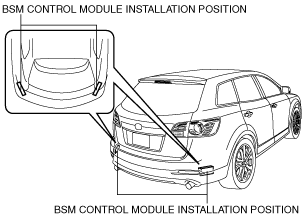
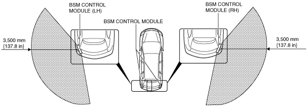
4. Verify that there is no obstruction within a 3,500 mm {137.8 in} radius from the BSM control module as shown in the figure.
ac9uuw00002821
|
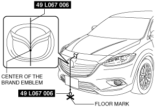
5. Adjust the SST (plum-bob) so that it is aligned with the center of the brand emblem, determine the center position at the front of the vehicle, and mark the center position on the floor surface.
ac9wzw00002736
|
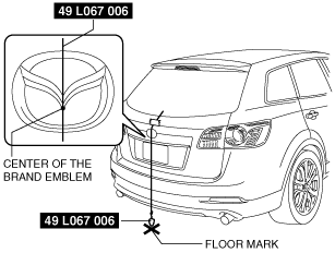
6. Adjust the SST (plum-bob) so that it is aligned with the center of the brand emblem, determine the center position at the rear of the vehicle, and mark the center position on the floor surface.
ac9wzw00002737
|
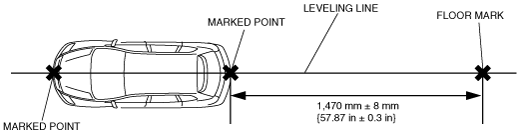
7. Position the leveling line over the marked positions at the front and rear of the vehicle, and then mark the position on the floor surface 1,470 mm ± 8 mm {57.87 in ± 0.3 in} from the vehicle rear.
ac9uuw00002824
|
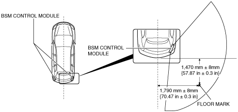
8. Mark the position on the floor where a right angle is formed by the lines which cross at the point 1,470 mm ± 8 mm {57.87 in ± 0.3 in} from the vehicle rear and the point 1,790 mm ± 8 mm {70.47 in ± 0.8 in} from the vehicle side which is perpendicular to the vehicle’s center line.
ac9uuw00002825
|
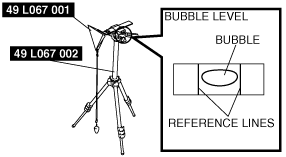
9. Set the SST (reflector) installation surface level using the bubble level built into the SST (tripod).
ac9uuw00003006
|
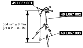
10. Install the SSTs (reflector and plum-bob) to the SST (tripod) and adjust the height of the reflector at its center to 534 mm ± 8 mm {21.0 in ± 0.3 in}.
ac9uuw00002826
|
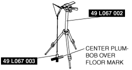
11. Verify visually that the reflecting surface of the reflector is facing the BSM control module, and position the SST (tripod) so that the SST (plum-bob) is positioned over the marked position.
ac9uuw00002828
|
ac9wzw00002738
|
12. Perform the BSM radar test according to the screen instructions using the IDS.
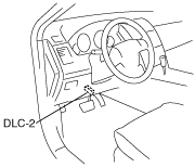
13. Connect the M-MDS (IDS) to the DLC-2.
ac9uuw00002676
|
14. After the vehicle is identified, select the following items from the initialization screen of the IDS.
15. Then, select items from the screen menu in the following order.
16. Perform the radar test according to the directions on the screen.
17. Verify the M-MDS display.
|
Step |
Inspection |
Action |
|
|---|---|---|---|
|
1
|
VERIFY REFLECTOR POSITION
• Verify if the reflector is set in the correct position.
(See Radar Test Procedure.)
• Is the reflector set in the correct position?
|
Yes
|
Go to the next step.
|
|
No
|
Set the reflector in the correct position and perform the BSM radar test.
(See Radar Test Procedure.)
|
||
|
2
|
RE-PERFORM BSM RADAR TEST
• Perform the BSM radar test.
• Repeat the BSM radar test up to four times until “TEST PASSED” is displayed.
(See Radar Test Procedure.)
• Is “TEST PASSED” displayed?
|
Yes
|
BSM radar test completed.
|
|
No
|
Go to the next step.
|
||
|
3
|
VERIFY EFFECT OF REAR BUMPER
• Remove the rear bumper. (See REAR BUMPER REMOVAL/INSTALLATION.)
• Perform the BSM radar test.
• Repeat the BSM radar test up to four times until “TEST PASSED” is displayed.
(See Radar Test Procedure.)
• Is “TEST PASSED” displayed?
|
Yes
|
Replace the rear bumper.
|
|
No
|
Go to the next step.
|
||
|
4
|
INSPECT BSM CONTROL MODULE FOR INCORRECT INSTALLATION AND DISTORTION AT VEHICLE INSTALLATION SURFACE
• Inspect the BSM control module for incorrect installation and distortion at the vehicle installation surface.
• Is the BSM control module installed correctly without distortion?
|
Yes
|
Go to the next step.
|
|
No
|
Repair or replace the malfunctioning part, then go to the next step.
|
||
|
5
|
PERFORM BSM RADAR TEST
• Perform the BSM radar test.
• Repeat the BSM radar test up to four times until “TEST PASSED” is displayed.
(See Radar Test Procedure.)
• Is “TEST PASSED” displayed?
|
Yes
|
BSM radar test completed.
|
|
No
|
Replace the BSM control module.
|
||