 |
ac9wzn00000828
ON-BOARD DIAGNOSTIC FUNCTION [CAN (CONTROLLER AREA NETWORK)]
id094000104100
On-Board Diagnostic Function
Malfunction detection function
Fail-safe function
Memory function
Self-malfunction diagnostic function
HS-CAN
|
DTC output module (M-MDS display) |
DTC |
Malfunction location |
|---|---|---|
|
PCM
(PCM)
|
U0101
|
Communication error to TCM
|
|
U0140
|
Communication error to BCM
|
|
|
TCM
(TCM)
|
U0073:00
|
CAN system communication error
|
|
U0100:00
|
Communication error to PCM
|
|
|
U0121:00
|
Communication error to DSC/RSC HU/CM
|
|
|
U0155:00
|
Communication error to instrument cluster
|
|
|
U0415:00
|
Abnormal message from DSC/RSC HU/CM
|
|
|
DSC/RSC HU/CM
(ABS)
|
U0073
|
CAN system communication error
|
|
U0100
|
Communication error to PCM
|
|
|
U0140
|
Communication error to BCM
|
|
|
U0155
|
Communication error to instrument cluster
|
|
|
BCM
(GEM)
|
U0073
|
CAN system communication error
|
|
U0100
|
Communication error to PCM
|
|
|
U0101
|
Communication error to TCM
|
|
|
U0121
|
Communication error to DSC/RSC HU/CM
|
|
|
U0401
|
Abnormal message from PCM
|
|
|
4WD control module*1
(4×4)
|
U0073
|
CAN system communication error
|
|
U0100
|
Communication error to PCM
|
|
|
U0101
|
Communication error to TCM
|
|
|
U0121
|
Communication error to DSC/RSC HU/CM
|
|
|
U0155
|
Communication error to instrument cluster
|
|
|
Keyless control module*2
(RKE)
|
U0073
|
CAN system communication error
|
|
U0100
|
Communication error to PCM
|
|
|
U0140
|
Communication error to BCM
|
|
|
U0323
|
Communication error to instrument cluster
|
|
|
U2023
|
Abnormal message from PCM
|
|
|
PLG control module*3
(LTM)
|
U0073
|
CAN system communication error
|
|
U0100
|
Communication error to PCM
|
|
|
U0101
|
Communication error to TCM
|
|
|
U0140
|
Communication error to BCM
|
|
|
U0155
|
Communication error to instrument cluster
|
|
|
U0214
|
Communication error to keyless control module
|
|
|
BSM control module (RH)*4
(BSMR)
|
U0001:88
|
CAN system communication error
|
|
U0100:00
|
Communication error to PCM
|
|
|
U0101:00
|
Communication error to TCM
|
|
|
U0140:00
|
Communication error to BCM
|
|
|
U0232:00
|
Communication error to BSM control module (LH)
|
|
|
U0401:68
|
Signal error from PCM
|
|
|
U0402:68
|
Signal error from TCM
|
|
|
U0422:68
|
Signal error from BCM
|
|
|
U0533:68
|
Signal error from BSM control module (LH)
|
|
|
BSM control module (LH)*4
(BSML)
|
U0001:88
|
CAN system communication error
|
|
U0100:00
|
Communication error to PCM
|
|
|
U0101:00
|
Communication error to TCM
|
|
|
U0140:00
|
Communication error to BCM
|
|
|
U0233:00
|
Communication error to BSM control module (RH)
|
|
|
U0401:68
|
Signal error from PCM
|
|
|
U0402:68
|
Signal error from TCM
|
|
|
U0422:68
|
Signal error from BCM
|
|
|
U0534:68
|
Signal error from BSM control module (RH)
|
|
|
Position memory control module*5
(DSM)
|
U0001:88
|
CAN system communication error
|
|
U0100:00
|
Communication error to PCM
|
|
|
U0101:00
|
Communication error to TCM
|
|
|
U0121:00
|
Communication error to DSC/RSC HU/CM
|
|
|
U0140:00
|
Communication error to BCM
|
|
|
U0155:00
|
Communication error to instrument cluster
|
|
|
U0431:68
|
Abnormal message from BCM
|
|
|
SAS control module
(RCM)
|
U0073
|
CAN system communication error
|
|
U0155
|
Communication error to instrument cluster
|
|
|
Theft-deterrent control module*6
(VSM)
|
U0001:88
|
CAN system communication error
|
|
U0100:00
|
Communication error to PCM
|
|
|
U0140:00
|
Communication error to BCM
|
|
|
Forward sensing camera*7
(FSC)
|
U0001:88
|
CAN system communication error
|
|
U0100:00
|
Communication error to PCM
|
|
|
U0121:00
|
Communication error to DSC/RSC HU/CM
|
|
|
U0140:00
|
Communication error to BCM
|
|
|
U0155:00
|
Communication error to instrument cluster
|
|
|
U0401:68
|
Abnormal message from PCM
|
|
|
U0415:68
|
Abnormal message from DSC/RSC HU/CM
|
|
|
U0422:68
|
Abnormal message from BCM
|
|
|
U0423:68
|
Abnormal message from instrument cluster
|
|
|
U2005:68
|
Abnormal message from PCM
|
|
|
Instrument cluster
(IC)
|
U0073
|
CAN system communication error
|
|
U0100
|
Communication error to PCM
|
|
|
U0101
|
Communication error to TCM
|
|
|
U0114
|
Communication error to 4WD control module
|
|
|
U0121
|
Communication error to DSC/RSC HU/CM
|
|
|
U0140
|
Communication error to BCM
|
|
|
U0151
|
Communication error to SAS control module
|
|
|
U0200
|
Communication error to BSM control module (RH)
|
|
|
U0214
|
Communication error to keyless control module
|
|
|
U023A
|
Communication error to forward sensing camera
|
|
|
U2510
|
Communication error to PCM
|
MS-CAN
|
DTC output module (M-MDS display) |
DTC |
Malfunction location |
|---|---|---|
|
Audio unit
(ACU)
|
U0010:88
(16:Er12)
|
CAN system communication error
|
|
BSM control module (LH)*1
(BSML)
|
U0010:88
|
CAN system communication error
|
|
U0100:00
|
Communication error to PCM
|
|
|
U0140:00
|
Communication error to BCM
|
|
|
Information display*2
|
01:Er
|
CAN system communication error
|
|
02:1E
|
Communication error to audio unit
|
|
|
02:3E
|
Communication error to instrument cluster
|
|
|
Information display*3
|
01Er
|
CAN system communication error
|
|
02 1E
|
Communication error to audio unit
|
|
|
02 3E
|
Communication error to instrument cluster
|
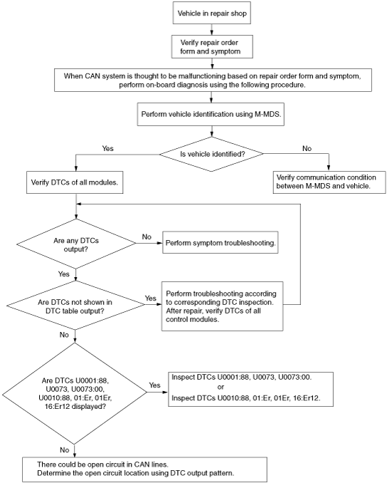
Narrowing down malfunction locations
Troubleshooting procedure
ac9wzn00000828
|
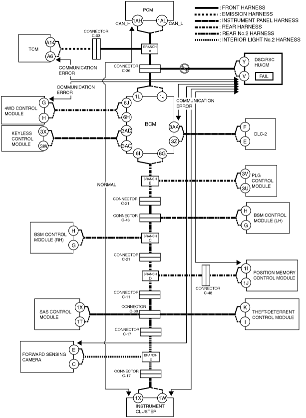
Example: DSC/RSC HU/CM-related wiring harness open circuit (if DTC is output)
1. Verify the CAN system-related module DTCs and the failed module using the Mazda Modular Diagnostic System (M-MDS).
|
Module |
Displayed DTC |
Probable malfunction location |
|---|---|---|
|
TCM (TCM)
|
U0121
|
Communication error to DSC/RSC HU/CM
|
|
GEM (BCM)
|
U0121
|
Communication error to DSC/RSC HU/CM
|
|
4X4 (4WD control module)
|
U0121
|
Communication error to DSC/RSC HU/CM
|
|
DSM (position memory control module)
|
U0121:00
|
Communication error to DSC/RSC HU/CM
|
|
FSC (forward sensing camera)
|
U0121:00
|
Communication error to DSC/RSC HU/CM
|
|
IC (instrument cluster)
|
U0121
|
Communication error to DSC/RSC HU/CM
|
|
Module |
Fail |
|---|---|
|
ABS (DSC/RSC HU/CM)
|
×
|
ac9wzn00000820
|
2. Despite normal communication between the PCM and instrument cluster, a communication error DTC is displayed for the signal between the DSC/RSC HU/CM and TCM/ BCM/ 4WD control module/ position memory control module/ forward sensing camera/ instrument cluster. In addition, the wiring harness between the DSC HU/CM and connector C-36 is considered to be malfunctioning because “Fail” is displayed for the DSC/RSC HU/CM.