LEAD-ACID BATTERY VOLTAGE SERVICE CAUTIONS
id000000702900
Electrical system handling
-
Caution
-
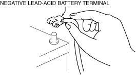
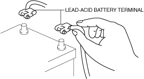
• When disconnecting the negative lead-acid battery terminal, be sure to switch the main power OFF and the headlight switch off. Otherwise, the semiconductor components may be damaged.
• When working on the electrical system, disconnect the negative lead-acid battery terminal.
• Never change or modify an electrical device or wiring arbitrarily. Otherwise, it may cause a vehicle fire due to a malfunction, over-capacity, or a short circuit.
-
Caution
-
• When disconnecting the negative lead-acid battery terminal, be sure to switch the main power OFF and the headlight switch off. Otherwise, the semiconductor components may be damaged.
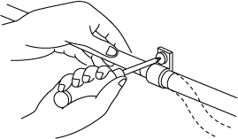
• When removing a wiring harness in the motor compartment, pry up the hook of the clip using a flathead screwdriver, detach the clip, and then remove the wiring harness.
-
Caution
-
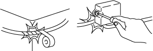
• Do not remove the tape protecting the wiring harness. Otherwise, the body may be rubbed by the wire causing water penetration or a short circuit.
• Clamp the wiring harness leaving no slack.
-
Caution
-
• Loosen areas of the wiring harness that cross vibrating parts and clamp them so that they do not contact surrounding areas that are vibrating.
• Do not throw or drop a unit, sensor, or relay.
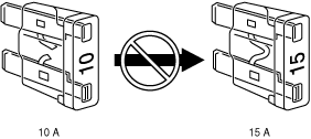
• If a fuse is blown, always replace it with one of the specified capacity.
-
Warning
-
• If a fuse larger than the specified capacity is used, it may cause part damage or a vehicle fire.
• Wrap the wiring harness with tape in areas which come into contact with edges and sharp corners of vehicle parts for protection.
• When installing parts, do not allow the wiring harness to get caught or damaged.
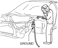
Welding Cautionary Notes
• Various electronic components are used in vehicles. In order to protect these parts from overcurrent generated during welding, the following must be strictly observed.
1. Switch the main power OFF.
2. Before welding, be sure to disconnect the positive and negative terminals of the lead-acid battery.
3. Connect the welding ground securely near the welding area.
4. Cover the parts surrounding the welding area during welding and be very careful of weld spatter.
Connector Handing
-
Caution
-
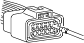
• If the wiring harness is pulled when disconnecting/connecting the connector, the terminal or the wire may be disconnected. When disconnecting/connecting a connector, always hold the connector with both hands.
Connector disconnection types
Connector connection inspection method
-
Caution
-
• Securely connect a connector to prevent poor contact with the terminal.
-
• Check for excessive play using a male terminal which matches the shape of female terminal.
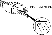
Terminal disconnection inspection method
-
Caution
-
• Verify that there is no disconnection from terminals to prevent poor contact with the terminal.
-
• Inspect the connectors while connected for terminals which may be sticking out from the wiring harness side.
-
• Inspect the terminals to verify that terminals do not pull out of the connectors when each wiring harness is pulled lightly one by one.
Methods of disconnecting from terminals
-
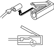
Control module connector
-
1. Release the rear cover.
2. Insert a flathead screwdriver and pull out the wiring harness with the stopper pressed up.
-
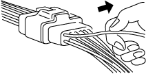
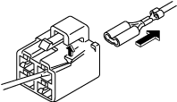
Multi-purpose connector
-
1. Insert a flathead screwdriver and pull out the wiring harness with the stopper pressed up.
-
Round type connector
-
1. Open the cover.
2. Pull out the terminal part upward.
3. When installing, verify that the terminal is securely connected to the connector.
-
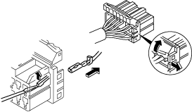
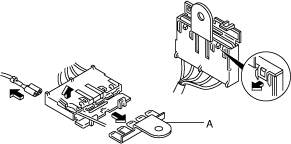
Common ground connector
-
1. Open the cover.
2. Pull out A shown in the figure.
3. Insert a flathead screwdriver and pull out the wiring harness with the stopper pressed up.
Measurement Device Handling
|
Measurement device
|
Purpose
|
Handling method
|
Handling cautions
|
|
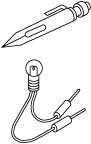
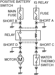
Test light
|
Use to facilitate search for open or short circuits
|
• Install test light between terminal and ground in circuit to be measured
• If the circuit is normal, the light will be on
|
• When making test lights, use only 12 V bulb (1.4 W or 3.4 W) or light emitting diodes (LEDs)
• If a bulb with a capacity higher than the specified capacity is used, it will burn out transistors, particularly in a control module.
|
 |
 |
|
Jumper wire
|
Use to operate switches and relays in circuits optionally
|
• Install jumper wire between terminals of switches and relays to be operated optionally
|
• Do not connect directly between power supply line and ground If it is connected directly, it may burn out wiring harnesses or damage electrical parts
|
 |
 |
|
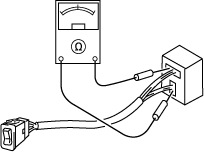
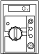
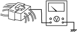
Voltmeter
|
Use when checking for open or short circuits by voltage, or electrical signals by voltage
|
• Set positive lead wire to voltage measurement location, negative lead wire to ground
|
• Connect voltmeter in parallel to circuit
• Use range appropriate to voltage to be measured
• When setting positive lead wire to narrow terminal, wrap thin wire around lead wire to set
|
 |
 |
|
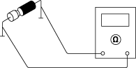
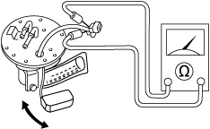
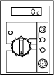
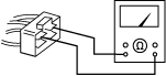
Ohmmeter
|
Use for verifying open or short circuits using continuity condition continuity of switches, or sensor resistance
-
Note
-
• Ohmmeter indicates continuity condition by replacing current flow with resistance when constant voltage is applied to measurement part.
|
• Perform zero reset
|
• Always perform zero reset after changing measuring range
• To prevent the ohmmeter from burning out, make sure that the main power is switched OFF and the negative lead-acid battery terminal is disconnected before use.
|
 |
 |
|
• Verify that power supply is not connected to circuit
• Set lead wire to inspection location
|
 |
|
Oscilloscope
|
Used for verifying control module input/output signal (wave pattern) condition
|
• Follow directions in Workshop Manual for measuring range and terminal
|
• Follow oscilloscope instruction manual and measure
|
 |
|
Ammeter
|
Used to inspect the back-up current in the circuit
Back-up current: The current that flows in the circuit even when the main power is switched OFF
|
• Connect positive lead wire to terminal on power supply side, negative lead wire to terminal on ground side in series with circuit
|
• Use range appropriate to current being measured
• Connect ammeter in series with circuit If ammeter is connected in parallel, it may burn out
|
 |
 |
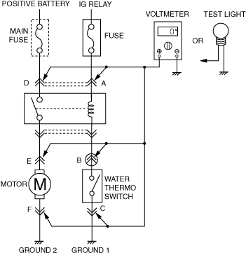
Voltage inspection
-
Inspection method
-
• Install the voltmeter or test light between the voltage measurement location and ground and measure the voltage.
×: Test light on
-: Test light off
|
Measurement location
|
During circuit normal operation
|
|
Main power position: OFF
|
Main power position: ON
|
|
Water thermoswitch: OFF
|
Water thermoswitch: ON
|
|
A
|
0 V -
|
VB×
|
VB×
|
|
B
|
0 V -
|
VB×
|
0 V -
|
|
C
|
0 V -
|
0 V -
|
0 V -
|
|
D
|
VB×
|
VB×
|
VB×
|
|
E
|
0 V -
|
0 V -
|
VB×
|
|
F
|
0 V -
|
0 V -
|
0 V -
|
Inspection note
-
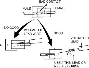
Measuring connector voltage
-
• If a thick voltmeter lead is inserted into the connector when there is a poor connector connection or a terminal disconnection, it may make contact with the terminal temporarily and the malfunction may not be detected. Therefore, use a thin lead or needle during voltage measurement.
-
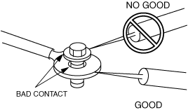
Measuring ground voltage
-
• When inspecting the ground circuit, apply the voltmeter lead to the ground wire to measure. Even if it is installed on the bolt side, poor ground cannot be found.
Continuity/resistance inspection
-
Caution
-
• Insert the lead from the back (harness side) to prevent damage to the terminal.
• For parts where the lead cannot be inserted from the back (waterproof connector, parts and connectors are integrated.), insert the lead from the terminal side, taking care not to damage the terminal.
-
Switch inspection
-
• Install the ohmmeter lead to the switch terminal and inspect for continuity.
-
Note
-
• Because the continuity of a switch differs depending on the switch operation conditions, inspect for continuity after verifying the operation conditions.
-
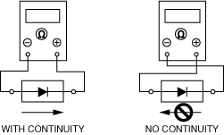
Diode inspection
-
• For circuits including diodes, inspect for continuity based on the direction in which the tester positive lead/negative lead is installed.
-
Note
-
• Pay attention to the polarity of the battery inside the ohmmeter and inspect the diode. If the polarity is wrong, the inspection cannot be performed correctly.
-
Sensor, solenoid, valve inspection
-
• Attach the lead of the ohmmeter to the sensor and valve terminals and measure the resistance.
-
Note
-
• Because the continuity of the sensor differs depending on the sensor operation conditions, inspect the resistance after verifying the conditions.
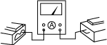
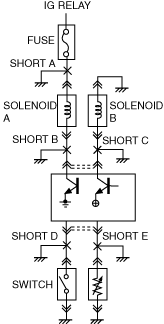
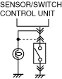
Short circuit detection method
-
• Detecting a short circuit requires determining which route the circuit has been established between the power supply side and ground side.
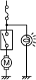
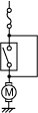
Circuit not connected to control module
|
|
Example
|
Short circuit detection method
|
|
Shorted location
|
Malfunction symptom
|
 |
Short A
|
• Fuse blown
|
 |
1. Remove fuse or main fuse for applicable circuit
2. Remove all connectors of electrical parts for applicable circuit
3. Install voltmeter or test light to fuse box, connect connector, and inspect voltage indicator or light illumination
|
 |
|
Short B
|
• Main fuse blown
|
 |
|
Short C
|
• Main power position: When ON (READY off), the motor operates regardless of the operation of the water thermoswitch
• Fuse is not blown
|
A short circuit has occurred at the place where the voltage indication changes when the connector is connected or at the place where the test light turns on.
|
|
Short D
|
• Main power position: When ON (READY off), water thermoswitch: ON, relay operating, the main fuse blows
|
Circuits connected to the control module
|
|
Example
|
Short circuit detection method
|
|
Shorted location
|
Malfunction symptom
|
 |
Short A
|
• Fuse blown
|
|
1. Remove fuse or main fuse for applicable circuit
2. Pull out all connectors of electrical parts for applicable circuit
3. Install voltmeter or test light to fuse box, connect connector, and inspect voltage indicator or light illumination
|
 |
|
Short B
|
• Main power position: When ON (READY off), solenoid A always operates
|
|
Short C
|
• Main power position: After ON (READY off), the transistor at the corresponding control module terminal burns out
|
A short circuit has occurred at the place where the voltage indication changes when the connector is connected or at the place where the test light turns on.
|
|
Short D
|
• Switch: The control module controls the switch: ON because the condition is the same as ON
|
 |
Install a test light or voltmeter to the control module connector, switch or sensor control module side connector in that order, and inspect the voltage indication or light illumination.
|
|
Short E
|
• The control module controls the sensor: 0 ohms because the same conditions as the sensor resistance value = 0 ohms apply The control module equipped with malfunction diagnostic function outputs DTC
|
A short circuit has occurred if the voltage indication is 0 V or the test light turns off
|
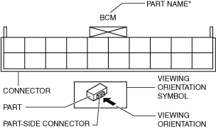
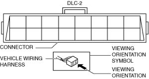
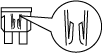
Connector viewing direction
• The connector viewing direction is indicated by a viewing direction symbol mark.
• The connector viewing direction indication is the same as the indication in the wiring diagram.
• There are three viewing directions as follows.
-
― Part-side connector
Visually inspect a part side connector from the terminal side.
*: Part names are indicated only if there are multiple connector figures for different parts in the same item
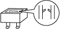
-
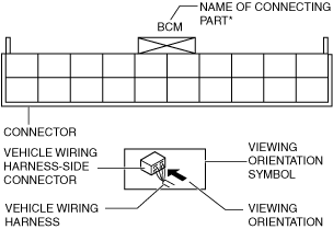
― Vehicle wiring harness side connector
Visually inspect vehicle wiring harness side connectors from the wiring harness side.
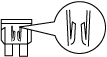
-
― Other
In the case of the following connectors that need to be seen from the terminal side in the vehicle wiring harness-side connector, they are seen from the terminal side.
*: With the wiring harness-side connector, connecting part names of all connectors are displayed in the figure.
-
• Main fuse block and relay in main fuse block
• Data link connector 2
• Check connector
• Relay box
*: Part names are indicated only if there are multiple connector figures for different parts in the same item.
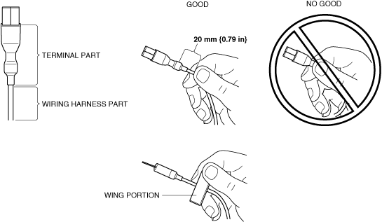
Female Terminal Fitting Test Procedure
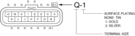
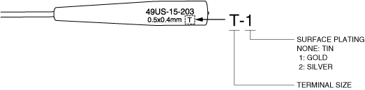
1. Refer to the wiring diagram and verify the location, size, and surface finish plating of the terminal to be tested.
2. Disconnect the negative lead-acid battery terminal.
3. Disconnect the connector of the terminal to be tested.
-
Caution
-
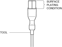
• When performing the fitting test, always use a tool compatible with the surface plating material of the terminal. The terminal surface plating is either gold, silver, or tin (None). Using a tool made of different material may damage the surface plating of the terminal. If the surface plating is damaged, the terminal may erode.
• Do not use a tool with scratched surface plating. Using a tool with scratched surface plating may damage the surface plating of the terminal. If the surface plating of the tool is damaged, replace the tool with a new one.
• Surface damage is difficult to see. Therefore, always use a magnifying glass when inspecting the condition of the surface plating.
4. Select a suitable tool from the fitting test kit with a size and surface plating that matches the terminal.
-
Caution
-
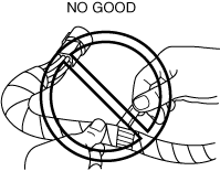
• Slowly insert the tool into the female terminal, and keep the tool in line with the terminal wherever possible.
• If the tool is inserted at an angle or wiggled into the female terminal, the terminal may be damaged.
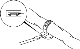
• Hold the wing portion of the tool with your fingers (if applicable), or the wiring harness, approximately 20 mm {0.79 in} away from the terminal portion of the tool. If the tool is inserted by holding the terminal portion of the tool, deformation of the female terminal opening can occur due to excessive force.
5. Insert the tool into the female terminal, then slowly pull it out.
-
• The inspection is completed if it can be determined that the terminal connection is good based on how firmly the tool can be inserted and removed.
-
Note
-
• Terminal size L is the largest size terminal tool. It may be difficult to insert it into a female terminal when holding the wiring harness due to excessive resistance. If it appears that the tool may be difficult to insert, confirm that the female terminal is in good condition, prior to inserting the tool.
-
― If the tool cannot be inserted or removed firmly and the condition of the female terminal cannot be determined, go to the next step.
-
Caution
-
• If the condition of the female terminal cannot be clearly determined, find the same size and surface treatment of the terminal in a different location to compare the connection firmness. Confirm the terminal location by referring to the wiring diagram.
6. Compare the connection firmness by inserting the tool into an identical terminal (same size and surface treatment) in the same connector.
-
• If the connection is not correct, replace the wiring harness or connectors including the malfunctioning terminal. (Refer to the repair connector replacement procedure.)
Ground inspection and disconnection/reconnection
• The ground connection is extremely important for normal electrical circuit operation, therefore, inspect and disconnect/reconnect the ground connection according to the following guidelines.
-
― Remove the bolt or screw of the ground to inspect for dirt or rust.
― If there is any dirt or rust, clean it.
― Securely tighten the bolt or screw to the specified tightening torque.
― Verify that parts do not interfere with the ground circuit.