49 H027 002
Bearing remover

49 T025 001
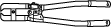
Boot clamp crimpers
49 UB71 525
Bearing installer

49 W032 310
Support block

49 0710 520
Universal bearing puller

—
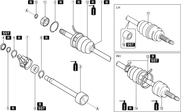
FRONT DRIVE SHAFT (DOUBLE OFFSET JOINT) DISASSEMBLY/ASSEMBLY
id031300700400
Special service tool (SST)
|
49 H027 002
Bearing remover
|
|
49 T025 001
Boot clamp crimpers
|
|
49 UB71 525
Bearing installer
|
|
|
49 W032 310
Support block
|
|
49 0710 520
Universal bearing puller
|
|
—
|
|
Replacement part
|
Boot band (EV transaxle side)
Quantity: 2
Location of use: Boot (EV transaxle side)
|
Dust cover
Quantity: 1
Location of use: Outer ring
|
Snap ring
Quantity: 1
Location of use: Outer ring
|
|
Snap ring
Quantity: 2
Location of use: Bracket
|
Clip
Quantity: 1
Location of use: Outer ring
|
Bearing
Quantity: 1
Location of use: Outer ring
|
|
Snap ring
Quantity: 1
Location of use: Double offset joint
|
Boot (EV transaxle side)
Quantity: 1
Location of use: Front drive shaft (EV transaxle side)
|
Boot band (wheel side)
Quantity: 2
Location of use: Boot (wheel side)
|
|
Boot (wheel side)
Quantity: 1
Location of use: Front drive shaft (wheel side)
|
—
|
—
|
Oil and chemical type
|
Grease
Type: Maintenance parts
|
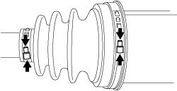
1. Disassemble in the order shown in the figure.
2. Assemble in the reverse order of disassembly.
a30zzw00006929
|
|
1
|
Boot band (EV transaxle side)
|
|
2
|
Clip
|
|
3
|
Outer ring
|
|
4
|
Dust cover
(See Dust Cover Disassembly Note.)
(See Dust Cover Assembly Note.)
|
|
5
|
Snap ring
|
|
6
|
Snap ring
|
|
7
|
Bracket
|
|
8
|
Snap ring
|
|
9
|
Bearing
(See Bearing Disassembly Note.)
(See Bearing Assembly Note.)
|
|
10
|
Snap ring
|
|
11
|
Ball, inner ring, cage
|
|
12
|
Boot (EV transaxle side)
|
|
13
|
Boot band (wheel side)
|
|
14
|
Boot (wheel side)
|
|
15
|
Shaft and ball joint component
|
|
16
|
Dynamic damper
(See Dynamic Damper Assembly Note.)
|
|
17
|
Outer joint component
|
Boot Band (EV transaxle Side) Disassembly Note
1. Grasp the boot band at the point shown in the figure using pliers, and remove the band.
a30jjw00003283
|
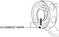
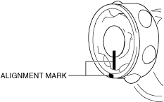
Clip, Outer Ring Disassembly Note
1. Place alignment marks on the shaft and outer ring.
am3zzw00036341
|
2. Remove the clip using a screwdriver.
atstjw00000061
|
3. Remove the outer ring from the shaft.
4. Wipe off grease on the outer ring using a clean cloth.
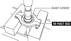
Dust Cover Disassembly Note
1. Remove the dust cover using a press and the SST.
am3uuw00011987
|
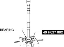
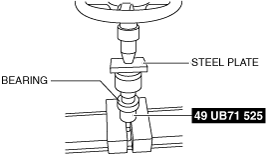
Bearing Disassembly Note
1. Remove the bearing using a press and the SST.
am3uuw00011988
|
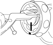
Snap ring, Ball, Inner Ring, Cage Disassembly Note
1. Place alignment marks on the shaft, inner ring, and cage.
am3zzw00031836
|
2. Remove the snap ring using snap ring pliers.
atstjw00000063
|
3. Remove the ball, inner ring, and cage from the shaft.
4. Wipe off grease on the shaft, ball, inner ring, and cage using a clean cloth.
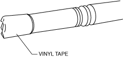
Boot (EV transaxle Side) Disassembly Note
1. Wrap vinyl tape around the spline area of the shaft to prevent damage to the boot.
azzzcw00000107
|
2. Remove the boot (EV transaxle side).
3. Wipe off grease on the boot (EV transaxle side) using a clean cloth.
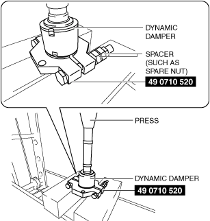
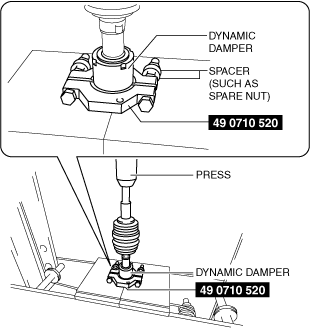
Dynamic Damper Disassembly Note
1. Remove the dynamic damper using the SST, a spacers (such as spare nuts), and a press.
am2zzw00007267
|
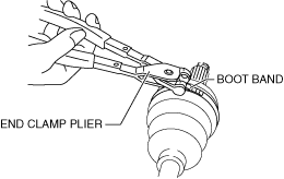
Boot Band (Wheel Side) Disassembly Note
1. Remove the boot band using end clamp pliers.
ac8wzw00002094
|
Boot (Wheel Side) Disassembly Note
1. Wrap vinyl tape around the spline area of the shaft to prevent damage to the boot.
azzzcw00000107
|
2. Remove the boot (wheel side).
3. Wipe off grease on the boot (wheel side) and ball joint using a clean cloth.
Boot (Wheel Side) Assembly Note
1. Install the boot with the vinyl tape left wrapped around the spline area of the shaft.
2. Apply the specified grease to the ball joint and boot (wheel side).
3. Assemble the boot (wheel side) to the ball joint.
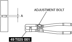
Boot Band (Wheel Side) Assembly Note
1. Adjust opening A of the SST to the standard by rotating the adjustment bolt.
ac8wzw00002095
|
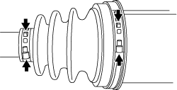
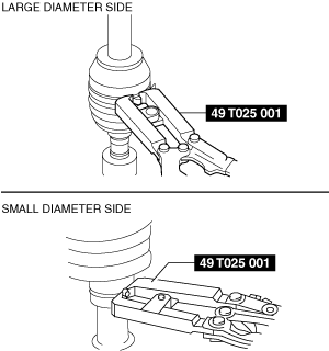
2. Crimp the boot band using the SST.
a30zzw00000265
|
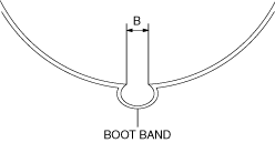
3. Verify that crimp B of the boot band is within the standard.
ac8wzw00002097
|
4. Verify that the boot band does not protrude from the band assembly area.
Dynamic Damper Assembly Note
1. Apply soapy water to the inside of the dynamic damper.
2. Assemble the dynamic damper using the SST, spacers (such as spare nuts), and a press.
am3zzw00023113
|
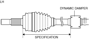
3. Verify that the installation position of the dynamic damper is within the specification.
a30zzw00000266
|
Boot (EV transaxle Side) Assembly Note
1. Insert the shaft through the boot (EV transaxle side) with vinyl tape left wrapped around the spline area of the shaft.
2. Remove vinyl tape wrapped around the spline area of the shaft.
Ball, Inner Ring, Cage, Snap Ring Assembly Note
1. Assemble the shaft, inner ring, and cage with the alignment marks aligned.
am3zzw00031837
|
2. Assemble a new snap ring using snap ring pliers.
atstjw00000063
|
3. Verify that the snap ring is assembled correctly in the groove of the shaft.
Bearing Assembly Note
1. Assemble a new bearing using the SST and a press.
am3uuw00011992
|
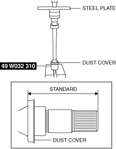
Dust Cover Assembly Note
1. Assemble a new dust cover using the SST and the press.
am3zzw00030181
|
2. Verify that the installation position of the dust cover is within the standard.
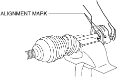
Outer Ring, Clip Assembly Note
1. Apply the specified grease to the outer ring and boot (EV transaxle side).
2. Assemble the outer ring with the alignment marks on the shaft and outer ring aligned.
ac30zw00004440
|
3. Assemble a new clip using a screwdriver.
atstjw00000061
|
4. Verify that the clip is assembled correctly in the groove of the outer ring.
5. Assemble the boot (EV transaxle side) to the outer ring.
6. Set the drive shaft length to the standard.
Drive shaft (double offset joint) full length (standard)
|
Full length (standard) |
|
|---|---|
|
LH
|
916.0—926.0 mm {36.07—36.45 in}
|
|
RH
|
754.2—764.2 mm {29.70—30.08 in}
|
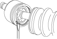
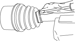
7. Release any trapped air from the boot by carefully lifting up the small end of the boot with a screwdriver wrapped in a clean cloth.
aatjjw00009777
|
8. Verify that the drive shaft length is within the standard when the inside of the boot is at atmospheric pressure.
Boot Band (EV transaxle Side) Assembly Note
1. Grasp the boot band at the point shown in the figure using pliers and tighten the boot band.
a30jjw00003284
|