 |
am3zzw00032150
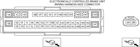
ELECTRONICALLY CONTROLLED BRAKE UNIT INSPECTION
id041900700300
1. Disconnect the electronically controlled brake unit connector. (See ELECTRONICALLY CONTROLLED BRAKE UNIT REMOVAL/INSTALLATION [L.H.D.].) (See ELECTRONICALLY CONTROLLED BRAKE UNIT REMOVAL/INSTALLATION [R.H.D.].)
2. Connect the negative Lead-acid battery terminal. (See NEGATIVE LEAD-ACID BATTERY TERMINAL DISCONNECTION/CONNECTION.)
3. Attach the tester lead to the electronically controlled brake unit wiring harness-side connector and inspect the voltage, continuity, or resistance according to the standard (reference) on the table.
Standard (Reference)
am3zzw00032150
|
|
Terminal |
Signal name |
Connected to |
Measured item |
Measured terminal (measurement condition) |
Standard |
Inspection item(s) |
|---|---|---|---|---|---|---|
|
1A
|
Power supply
|
Battery
|
Voltage
|
Under any condition
|
B+
|
• Wiring harness (1A—Battery positive terminal)
|
|
1B
|
—
|
—
|
—
|
—
|
—
|
—
|
|
1C
|
Electric parking brake motor gear unit (RH)
|
Electric parking brake motor gear unit (RH)
|
Continuity
|
1C—Electric parking brake motor gear unit (RH) terminal B
|
Continuity detected
|
• Wiring harness (1C—Electric parking brake motor gear unit (RH) terminal B)
|
|
1D
|
CAN2_H
|
CAN module
|
This terminal is used for communication and cannot be used for malfunction determination during terminal voltage inspection. Perform a DTC inspection.
|
|||
|
1E
|
Stop signal
|
Electrical supply unit
|
Continuity
|
1E—Electrical supply unit terminal 3L
|
Continuity detected
|
• Wiring harness (1E—Electrical supply unit terminal 3L)
|
|
1F
|
CAN2_L
|
CAN module
|
This terminal is used for communication and cannot be used for malfunction determination during terminal voltage inspection. Perform a DTC inspection.
|
|||
|
1G
|
—
|
—
|
—
|
—
|
—
|
—
|
|
1H
|
Electric parking brake motor gear unit (RH)
|
Electric parking brake motor gear unit (RH)
|
Continuity
|
1H—Electric parking brake motor gear unit (RH) terminal A
|
Continuity detected
|
• Wiring harness (1H—Electric parking brake motor gear unit (RH) terminal A)
|
|
1I
|
Electric parking brake switch
|
Electric parking brake switch
|
Continuity
|
1I—Electric parking brake switch terminal D
|
Continuity detected
|
• Wiring harness (1I—Electric parking brake switch terminal D)
|
|
1J
|
Electric parking brake switch indicator light
|
Electric parking brake switch indicator light (built into electric parking brake switch)
|
Continuity
|
1J—Electric parking brake switch terminal F
|
Continuity detected
|
• Wiring harness (1J—Electric parking brake switch terminal F)
|
|
1K
|
Electric parking brake switch
|
Electric parking brake switch
|
Continuity
|
1K—Electric parking brake switch terminal H
|
Continuity detected
|
• Wiring harness (1K—Electric parking brake switch terminal H)
|
|
1L
|
—
|
—
|
—
|
—
|
—
|
—
|
|
1M
|
RF wheel-speed sensor (-)
|
ABS wheel-speed sensor (RF)
|
Continuity
|
1M—ABS wheel-speed sensor (RF) terminal A
|
Continuity detected
|
• Wiring harness (1M—ABS wheel-speed sensor (RF) terminal A)
|
|
1N
|
Electric parking brake switch
|
Electric parking brake switch
|
Continuity
|
1N—Electric parking brake switch terminal I
|
Continuity detected
|
• Wiring harness (1N—Electric parking brake switch terminal I)
|
|
1O
|
Power supply (system)
|
IG1 relay No.2
|
Voltage
|
Main power ON (READY off or on)
|
B+
|
• Wiring harness (1O—IG1 relay No.2 terminal C)
|
|
Main power OFF
|
1 V or less
|
|||||
|
1P
|
RF wheel-speed sensor (+)
|
ABS wheel-speed sensor (RF)
|
Continuity
|
1P—ABS wheel-speed sensor (RF) terminal B
|
Continuity detected
|
• Wiring harness (1P—ABS wheel-speed sensor (RF) terminal B)
|
|
1Q
|
Electric parking brake switch
|
Electric parking brake switch
|
Continuity
|
1Q—Electric parking brake switch terminal E
|
Continuity detected
|
• Wiring harness (1Q—Electric parking brake switch terminal E)
|
|
1R
|
—
|
—
|
—
|
—
|
—
|
—
|
|
1S
|
LR wheel-speed sensor (-)
|
ABS wheel-speed sensor (LR)
|
Continuity
|
1S—ABS wheel-speed sensor (LR) terminal D
|
Continuity detected
|
• Wiring harness (1S—ABS wheel-speed sensor (LR) terminal D)
|
|
1T
|
—
|
—
|
—
|
—
|
—
|
—
|
|
1U
|
—
|
—
|
—
|
—
|
—
|
—
|
|
1V
|
LR wheel-speed sensor (+)
|
ABS wheel-speed sensor (LR)
|
Continuity
|
1V—ABS wheel-speed sensor (LR) terminal B
|
Continuity detected
|
• Wiring harness (1V—ABS wheel-speed sensor (LR) terminal B)
|
|
1W
|
—
|
—
|
—
|
—
|
—
|
—
|
|
1X
|
—
|
—
|
—
|
—
|
—
|
—
|
|
1Y
|
LF wheel-speed sensor (-)
|
ABS wheel-speed sensor (LF)
|
Continuity
|
1Y—ABS wheel-speed sensor (LF) terminal A
|
Continuity detected
|
• Wiring harness (1Y—ABS wheel-speed sensor (LF) terminal A)
|
|
1Z
|
—
|
—
|
—
|
—
|
—
|
—
|
|
1AA
|
—
|
—
|
—
|
—
|
—
|
—
|
|
1AB
|
LF wheel-speed sensor (+)
|
ABS wheel-speed sensor (LF)
|
Continuity
|
1AB—ABS wheel-speed sensor (LF) terminal B
|
Continuity detected
|
• Wiring harness (1AB—ABS wheel-speed sensor (LF) terminal B)
|
|
1AC
|
—
|
—
|
—
|
—
|
—
|
—
|
|
1AD
|
—
|
—
|
—
|
—
|
—
|
—
|
|
1AE
|
RR wheel-speed sensor (-)
|
ABS wheel-speed sensor (RR)
|
Continuity
|
1AE—ABS wheel-speed sensor (RR) terminal D
|
Continuity detected
|
• Wiring harness (1AE—ABS wheel-speed sensor (RR) terminal D)
|
|
1AF
|
Brake fluid level sensor
|
Brake fluid level sensor
|
Continuity
|
1AF—brake fluid level sensor terminal A
|
Continuity detected
|
• Wiring harness (1AF—brake fluid level sensor terminal A)
|
|
1AG
|
—
|
—
|
—
|
—
|
—
|
—
|
|
1AH
|
RR wheel-speed sensor (+)
|
ABS wheel-speed sensor (RR)
|
Continuity
|
1AH—ABS wheel-speed sensor (RR) terminal B
|
Continuity detected
|
• Wiring harness (1AH—ABS wheel-speed sensor (RR) terminal B)
|
|
1AI
|
—
|
—
|
—
|
—
|
—
|
—
|
|
1AJ
|
—
|
—
|
—
|
—
|
—
|
—
|
|
1AK
|
Electric parking brake motor gear unit (LH)
|
Electric parking brake motor gear unit (LH)
|
Continuity
|
1AK—Electric parking brake motor gear unit (LH) terminal A
|
Continuity detected
|
• Wiring harness (1AK—Electric parking brake motor gear unit (LH) terminal A)
|
|
1AL
|
Brake fluid level sensor
|
Brake fluid level sensor
|
Continuity
|
1AL—brake fluid level sensor terminal B
|
Continuity detected
|
• Wiring harness (1AL—brake fluid level sensor terminal B)
|
|
1AM
|
CAN1_H
|
CAN module
|
This terminal is used for communication and cannot be used for malfunction determination during terminal voltage inspection. Perform a DTC inspection.
|
|||
|
1AN
|
—
|
—
|
—
|
—
|
—
|
—
|
|
1AO
|
CAN1_L
|
CAN module
|
This terminal is used for communication and cannot be used for malfunction determination during terminal voltage inspection. Perform a DTC inspection.
|
|||
|
1AP
|
Electric parking brake motor gear unit (LH)
|
Electric parking brake motor gear unit (LH)
|
Continuity
|
1AP—Electric parking brake motor gear unit (LH) terminal B
|
Continuity detected
|
• Wiring harness (1AP—Electric parking brake motor gear unit (LH) terminal B)
|
|
1AQ
|
—
|
—
|
—
|
—
|
—
|
—
|
|
1AR
|
—
|
—
|
—
|
—
|
—
|
—
|
|
1AS
|
Ground
|
Ground point
|
Continuity
|
1AS—Ground point
|
Continuity detected
|
• Wiring harness (1AS—Ground point)
|
|
1AT
|
—
|
—
|
—
|
—
|
—
|
—
|
|
2A
|
Ground
|
Ground point
|
Continuity
|
2A—Ground point
|
Continuity detected
|
• Wiring harness (2A—Ground point)
|
|
2B
|
Power supply
|
Battery
|
Voltage
|
Under any condition
|
B+
|
• Wiring harness (2B—Battery positive terminal)
|