EBD CONTROL
id041900701700
Outline
• The EBD control distributes brake fluid pressure to the rear wheels using the ABS system, and the rear wheels lock before the front wheels during braking to prevent loss of steering stability.
Features
• The EBD control has an independent control system for the front and rear wheels.
• The EBD control constantly distributes optimal brake fluid pressure regardless of the vehicle weight.
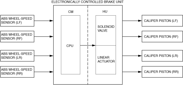
Construction
Block diagram
Operation
• The EBD control detects the estimated vehicle speed and the slip ratio of the rear wheel speed based on the signal from the ABS wheel-speed sensors. When the slip ratio of the rear wheels increases to the specified value or more relative to the front wheels, the electronically controlled brake unit controls the rear wheel brake pressure. Therefore, the distribution of brake fluid pressure to the front and rear wheels can be constantly and optimally controlled according to the vehicle load, road conditions and the vehicle speed.
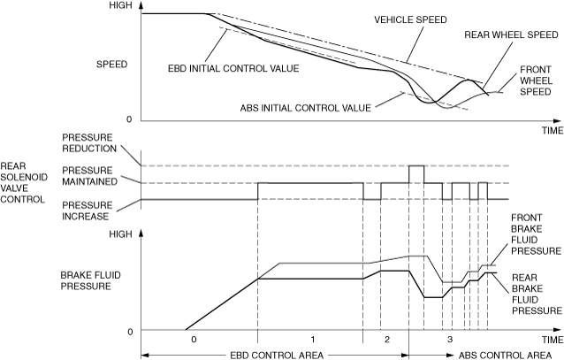
• The electronically controlled brake unit determines the rear wheel slip ratio by comparing the minimum wheel speed of the front wheels and the estimated vehicle speed with the wheel speed of the rear wheels, and groups the EBD control status into a level between 0 and 3 in the table below according to the determination result.
• The electronically controlled brake unit HU outlet and inlet solenoid valves are operated and the brake fluid pressure is controlled according to the divided status.
• If the ABS control conditions are met during EBD control, the EBD control is canceled and the ABS control is given priority.
|
Status
|
Rear wheel slip ratio determination
|
EBD control
|
Solenoid valve
|
Comment
|
|
0
|
No slip
|
Non-control
|
Pressure increase
|
—
|
|
1
|
α%—β%
|
Control
|
Maintained
|
—
|
|
2
|
After EBD control, slip ratio is γ %
|
Control
|
Pressure increase/maintained
|
—
|
|
3
|
Front wheel slip ratio is δ or more
|
Control
|
Pressure decrease/maintained/pressure increase
|
ABS control operates
|
α—δ :Specification
Control status transition diagram