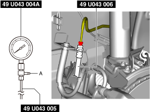
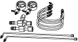
49 U043 004A
Oil pressure gauge
(Part of 49 U043 0A0A)

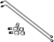
49 U043 005
Joint
(Part of 49 U043 0A0A)
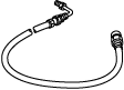
49 U043 006
Hose
(Part of 49 U043 0A0A)
49 U043 0A0A
Oil pressure gauge set
—
—
BRAKE FLUID PRESSURE SENSOR INSPECTION
id041900703500
|
49 U043 004A
Oil pressure gauge
(Part of 49 U043 0A0A)
|
|
49 U043 005
Joint
(Part of 49 U043 0A0A)
|
|
49 U043 006
Hose
(Part of 49 U043 0A0A)
|
|
|
49 U043 0A0A
Oil pressure gauge set
|
|
—
|
—
|
||
1. Switch the main power OFF.
2. Remove the wheel and tire. (See WHEEL AND TIRE REMOVAL/INSTALLATION.)
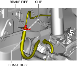
3. Disconnect the brake pipe from the brake hose.
am3zzw00025068
|
4. Remove the clip.
5. Remove the brake hose from the bracket.
6. Install the SSTs to the brake pipe as shown in the figure.
am3zzw00025069
|
7. Bleed the brake line and the SSTs of air. Bleed the air form the SSTs using bleeder screw A.
8. Connect the M-MDS to the DLC-2.
9. Display electronically controlled brake unit PID BRK_FLD_PRES. (See PID/DATA MONITOR INSPECTION.) (See PID/DATA MONITOR TABLE [ELECTRONICALLY CONTROLLED BRAKE UNIT].)
10. Switch the main power ON (READY on).
11. Depress the brake pedal, and confirm that the fluid pressure value of the SST (gauge) and the value shown on the M-MDS are equal
12. After the inspection, remove the SSTs, install the brake hose, clamp, and brake pipe to the original positions, and then bleed the air from the brake line. (See FRONT BRAKE HOSE REMOVAL/INSTALLATION.)