49 T028 3A0
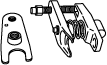
Ball joint puller set
TIE-ROD END REMOVAL/INSTALLATION
id061300701100
Special service tool (SST)
|
49 T028 3A0
Ball joint puller set
|
|
Replacement part
|
Snap pin
Quantity: 1
Location of use: Tie-rod end
|
Removal
1. Remove the wheel and tire. (See WHEEL AND TIRE REMOVAL/INSTALLATION.)
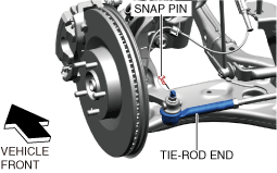
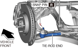
2. Remove the snap pin from the tie-rod end.
a30zzw00002163
|
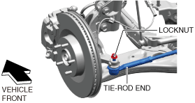
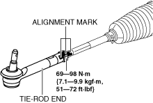
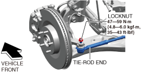
3. Loosen the locknut of the tie-rod end.
a30zzw00002164
|
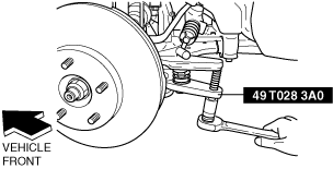
4. Detach the tie-rod end from the steering knuckle using the SST.
ac8wzw00001479
|
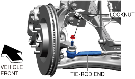
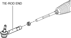
5. Remove the locknut of the tie-rod end.
a30zzw00002165
|
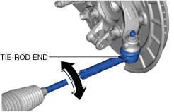
6. Place alignment marks as shown in the figure for reference in tie-rod end assembly.
ac30zw00001985
|
7. Remove the tie-rod end.
ac30zw00001986
|
Installation
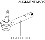
1. Place alignment marks on the new tie-rod end in the same positions as the removed tie-rod end.
ac30zw00001987
|
2. Align the alignment marks that were made before removing the tie-rod end, and assemble the tie-rod end to the tie rod.
ac30zw00001985
|
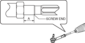
3. Verify that dimension A shown in the figure is within the standard.
ac30zw00000519
|
4. Install the tie-rod end to the steering knuckle.
a30zzw00002166
|
5. Install a new snap pin.
ac30zw00000521
|
6. Install the wheel and tire. (See WHEEL AND TIRE REMOVAL/INSTALLATION.)
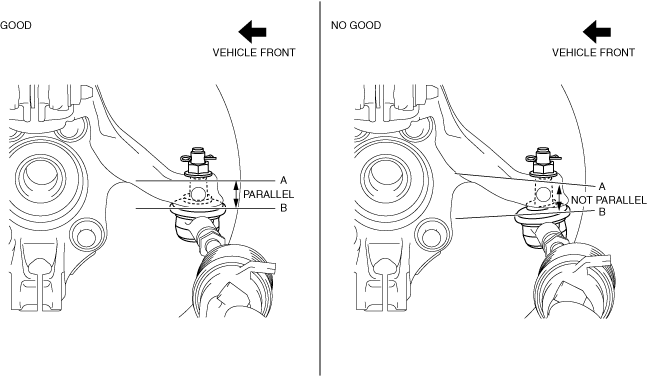
7. Verify that A and B shown in the figure are parallel while the vehicle is on the ground.
ac30zw00001988
|
ac30zw00000523
|
8. After installation, inspect the front wheel alignment. (See FRONT WHEEL ALIGNMENT.)