 |
atstjt00000003
ELECTRIC POWER STEERING SYSTEM
id061300701600
Outline
Specifications
|
Item |
Specification |
|||
|---|---|---|---|---|
|
Steering wheel
|
Outer diameter
|
(mm {in})
|
372 {14.6}
|
|
|
Lock to lock
|
(turns)
|
2.82
|
||
|
Steering column and shaft
|
Shaft type
|
Collapsible
|
||
|
Joint type
|
Cross-shaped joint
|
|||
|
Tilt amount
|
(mm {in})
|
45 {1.8}
|
||
|
Telescope amount
|
(mm {in})
|
70 {2.8}
|
||
|
Steering gear and linkage
|
Type
|
Rack-and-pinion
|
||
|
Rack stroke
|
(mm {in})
|
149.2 mm {5.874 in}
|
||
|
Power steering system
|
Power assist type
|
Electric motor assist (Column assist type)
|
||
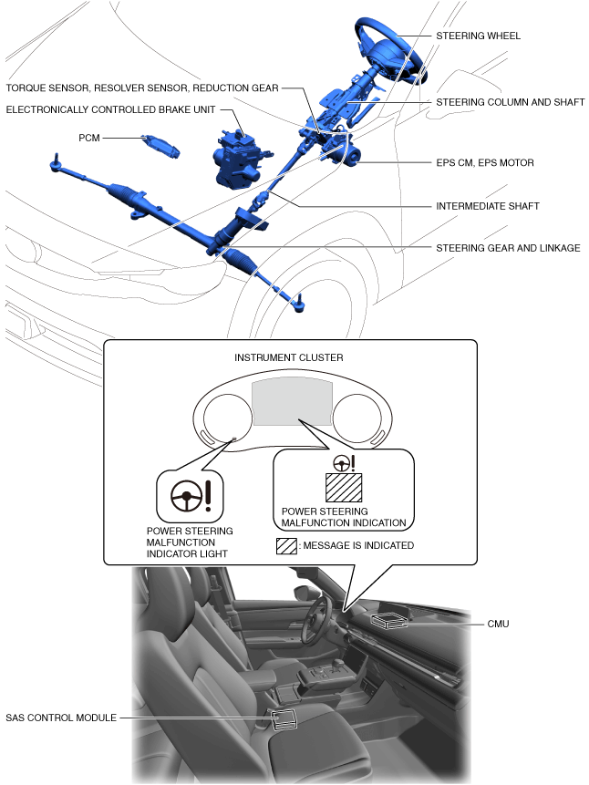
Purpose, Function
Construction
|
Part name |
Functions |
|---|---|
|
EPS CM
|
• Calculates the optimum assist force based on the signals from the torque sensor, EPS motor, PCM, electronically controlled brake unit and SAS control module, and outputs the EPS motor drive current.
• After the vehicle begins moving, the system performs self-learning of the steering angle neutral position based on the signals from the electronically controlled brake unit and the SAS control module, and outputs it as a steering angle (estimated absolute steering angle) signal to CAN.
• Outputs an power steering malfunction indication on request signal to CAN when there is a malfunction in the EPS system.
|
|
PCM
|
• Transmits an electric motor speed signal to the EPS CM via CAN communication.
|
|
Electronically controlled brake unit
|
• Transmits a vehicle wheel speed signal, vehicle speed signal, vehicle lateral-G (vehicle lateral acceleration speed) and yaw rate (vehicle turning angle speed) to the EPS CM via CAN communication.
|
|
SAS control module
|
• Transmits the signal from the steering angle sensor to the EPS CM as a steering angle (absolute steering angle) signal via CAN communication.
|
|
Instrument cluster
|
• Alerts the driver that there is a malfunction in the EPS system by turning on the electric power steering warning indication based on the electric power steering warning light/electric power steering warning indication on request signal output by the EPS CM.
|
|
CMU
|
• Alerts the driver that there is a malfunction in the EPS system by turning on the electric power steering warning indication based on the electric power steering warning light/electric power steering warning indication on request signal output by the EPS CM.
|
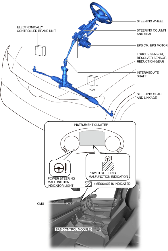
Structural View
L.H.D.
atstjt00000003
|
R.H.D.
a30zzn00001605
|
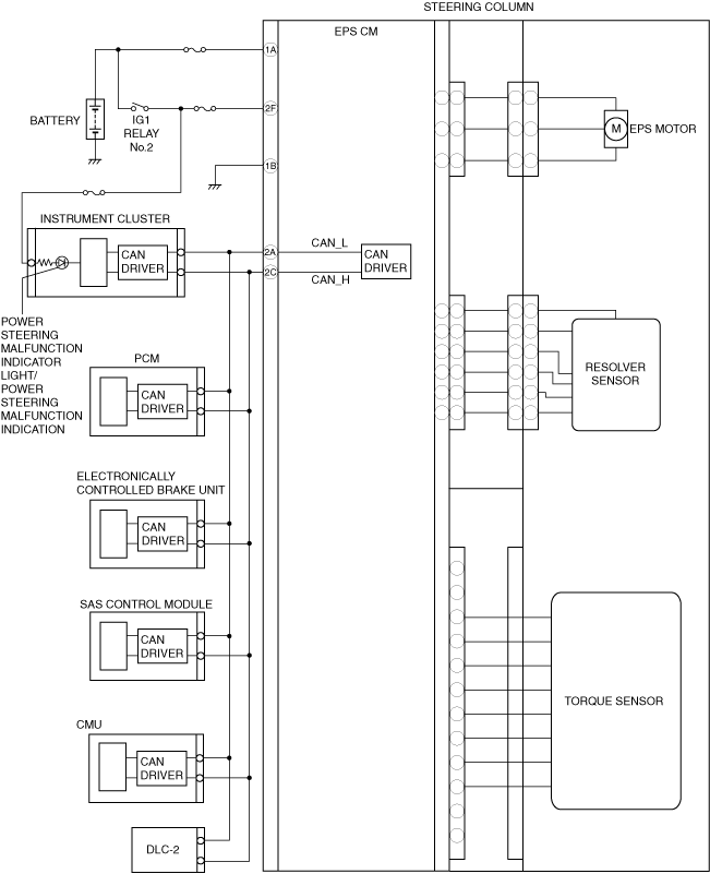
System Wiring Diagram
a30zzn00000041
|
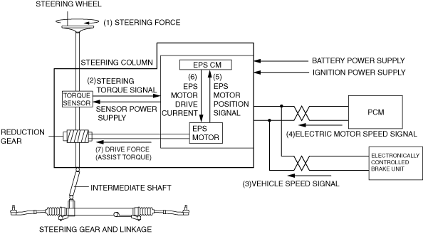
Operation
1. Steering force (1) generated by the driver's steering wheel operation is detected by the torque sensor built into the steering column and shaft, and it is output (2) to the EPS CM as a steering torque signal.
2. The EPS CM calculates optimum assist force based on the steering torque signal (2) from the torque sensor, the vehicle speed signal (3) from the electronically controlled brake unit, electric motor speed signal (4) from the PCM, and EPS motor position signal (5) from the EPS motor, and outputs (6) electric current to drive the EPS motor.
3. The EPS motor drive force (assist torque) generated by the EPS motor drive current (6) from the EPS CM is transmitted (7) to the intermediate shaft via the reduction gear to assist the driver's steering operation.
a30zzn00000042
|