 |
a30jjw00000111
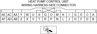
HEAT PUMP CONTROL UNIT INSPECTION [FULL-AUTO AIR CONDITIONER]
id0740a1702500
1. Disconnect the negative lead-acid battery terminal. (See NEGATIVE LEAD-ACID BATTERY TERMINAL DISCONNECTION/CONNECTION.)
2. Remove the heat pump control unit with the connector connected.
3. Connect the negative lead-acid battery terminal. (See NEGATIVE LEAD-ACID BATTERY TERMINAL DISCONNECTION/CONNECTION.)
4. Connect the negative lead of the tester to the body ground.
5. Insert the positive lead into the heat pump control unit and measure the voltage of each terminal following the terminal voltage table.
Terminal voltage table (reference)
a30jjw00000111
|
|
Terminal |
Signal name |
Connection |
Measurement condition |
Voltage (V) |
Inspection items |
|---|---|---|---|---|---|
|
A
|
IG
|
A/C relay
|
Main power is switched to ACC or ON (READY off)
|
VB
|
• Lead-acid battery
• F11 7.5A fuse
• A/C relay
• Related wiring harness
|
|
Main power is switched OFF
|
1.0 or less
|
||||
|
B
|
BATT
|
F11 7.5A fuse
|
Continuous
|
VB
|
• Lead-acid battery
• F11 7.5A fuse
|
|
C
|
CAN_H
|
CAN related module
|
Because this terminal is for communication, examination using terminal voltage inspection is not possible. Perform inspection using the DTC inspection.
|
• Related wiring harness
|
|
|
D
|
—
|
—
|
—
|
—
|
—
|
|
E
|
CAN_L
|
CAN related module
|
Because this terminal is for communication, examination using terminal voltage inspection is not possible. Perform inspection using the DTC inspection.
|
• Related wiring harness
|
|
|
F
|
GND1
|
Body ground
|
Continuous
|
Approx. 0
|
• GND point
• Related wiring harness
|
|
G
|
—
|
—
|
—
|
—
|
—
|
|
H
|
—
|
—
|
—
|
—
|
—
|
|
I
|
CL_MGVLV_2WAY
|
2way valve for refrigerant
|
Connect the M-MDS and turn on the [2_WAY_VLV] using the heat pump control unit simulation function.
|
1.0 or less
|
• 2way valve for refrigerant
• Related wiring harness
|
|
Connect the M-MDS and turn off the [2_WAY_VLV] using the heat pump control unit simulation function.
|
VB
|
||||
|
J
|
—
|
—
|
—
|
—
|
—
|
|
K
|
HT_MGVLV_3WAY
|
3way valve for refrigerant
|
Connect the M-MDS and turn on the [3_WAY_VLV] using the heat pump control unit simulation function.
|
1.0 or less
|
• 3way valve for refrigerant
• Related wiring harness
|
|
Connect the M-MDS and turn off the [3_WAY_VLV] using the heat pump control unit simulation function.
|
VB
|
||||
|
L
|
—
|
—
|
—
|
—
|
—
|
|
M
|
—
|
—
|
—
|
—
|
—
|
|
N
|
—
|
—
|
—
|
—
|
—
|
|
O
|
—
|
—
|
—
|
—
|
—
|
|
P
|
—
|
—
|
—
|
—
|
—
|
|
Q
|
—
|
—
|
—
|
—
|
—
|
|
R
|
—
|
—
|
—
|
—
|
—
|
|
S
|
SUCS_TEMP_SSR
|
Temperature sensor of refrigerant line for condenser outlet
|
—
|
Voltage cannot be measured.
|
• Temperature sensor of refrigerant line for condenser outlet
• Related wiring harness
|
|
T
|
—
|
—
|
—
|
—
|
—
|
|
U
|
EVA_OUT_TEMP_SSR
|
temperature sensor of refrigerant line for evaporator outlet
|
—
|
Voltage cannot be measured.
|
• Temperature sensor of refrigerant line for evaporator outlet
• Related wiring harness
|
|
V
|
GND_SSR
|
• Temperature sensor of refrigerant line for condenser outlet
• Temperature sensor of refrigerant line for evaporator outlet
|
Continuous
|
1.0 or less
|
• Temperature sensor of refrigerant line for condenser outlet
• Temperature sensor of refrigerant line for evaporator outlet
• Related wiring harness
|
|
W
|
—
|
—
|
—
|
—
|
—
|
|
X
|
GND2
|
Body ground
|
Continuous
|
Approx. 0
|
• GND point
• Related wiring harness
|
|
Y
|
—
|
—
|
—
|
—
|
—
|
|
Z
|
CL_ExpVLV_B2
|
Electric expansion valve
|
—
|
Voltage cannot be measured.
|
• Electric expansion valve
• Related wiring harness
|
|
AA
|
—
|
—
|
—
|
—
|
—
|
|
AB
|
CL_ExpVLV_B1
|
Electric expansion valve
|
—
|
Voltage cannot be measured.
|
• Electric expansion valve
• Related wiring harness
|
|
AC
|
—
|
—
|
—
|
—
|
—
|
|
AD
|
CL_ExpVLV_A2
|
Electric expansion valve
|
—
|
Voltage cannot be measured.
|
• Electric expansion valve
• Related wiring harness
|
|
AE
|
—
|
—
|
—
|
—
|
—
|
|
AF
|
CL_ExpVLV_A1
|
Electric expansion valve
|
—
|
Voltage cannot be measured.
|
• Electric expansion valve
• Related wiring harness
|