 |
a30zzw00000888
SNAPSHOT DATA TABLE [SAS CONTROL MODULE (TWO-STEP DEPLOYMENT CONTROL SYSTEM) (E)]
id0802i2706200
Snapshot Data Table
|
Snapshot data item |
Unit |
Definition |
Data read/use method |
Corresponding PID data monitor item |
|
|---|---|---|---|---|---|
|
AMB_TEMP
|
°C
|
Ambient temperature
|
―
|
―
|
|
|
FAULT_OCCURRENCE_TIMES
|
―
|
Number of malfunction detections
|
―
|
―
|
|
|
FIRST_FAULT_DETECT
|
hh:mm:ss*1
|
Time when initial malfunction occurs (main power ON counter)
• Elapsed time from when main power is switched ON (READY off or on) until SAS control module detects first malfunction detects first malfunction
(See Snapshot counter pattern.)
|
―
|
―
|
|
|
GLOBAL_REAL_TIME
|
min
|
Global real time
|
―
|
―
|
|
|
IG_ON_TIMER
|
hh:mm:ss*1
|
Elapsed time since main power was switched ON (READY off or on)
|
• If a DTC is detected, the SAS control module records the elapsed time since the main power was switched ON (READY off or on) when the DTC was detected, and it is displayed in the M-MDS.
|
―
|
|
|
LAST_FAULT_DETECT
|
hh:mm:ss*1
|
Repair time for last malfunction (B+ counter)
• Elapsed time from when battery is connected until SAS control module detects that last malfunction is repaired
(See Snapshot counter pattern.)
|
―
|
―
|
|
|
LAST_FAULT_CLEAR
|
hh:mm:ss*1
|
Repair time for last malfunction (main power ON counter)
• Elapsed time from when main power is switched ON (READY off or on) until SAS control module detects that last malfunction is repaired
(See Snapshot counter pattern.)
|
―
|
―
|
|
|
LAST_FAULT_DETECT_IG_ON
|
hh:mm:ss*1
|
Time when last malfunction occurs (B+ counter)
• Elapsed time from when battery is connected until SAS control module detects last malfunction
(See Snapshot counter pattern.)
|
―
|
―
|
|
|
LAST_FAULT_CLEAR_IG_ON
|
hh:mm:ss*1
|
Time when last malfunction occurs (main power ON counter)
• Elapsed time from when main power is switched ON (READY off or on) until SAS control module detects last malfunction
(See Snapshot counter pattern.)
|
―
|
―
|
|
|
POWER_MODE
|
OFF/ACC/ON
|
OFF: Main power is switched to OFF
ACC: Main power is switched to ACC
ON: Main power is switched to ON (READY off or on)
|
• The SAS control module constantly receives the main power switch status sent via CAN signal from the instrument cluster.
• If a DTC is detected, the SAS control module records the main power switch status when the DTC was detected, and it is displayed in the M-MDS.
|
―
|
|
|
TOTAL_DIST
|
km
|
Accumulated total traveled distance from completion of vehicle until SAS control module detects DTC (Odometer value in instrument cluster)
|
The total traveled distance from which the SAS control module detects DTCs to the present can be calculated by performing the following procedure.
1. Verify the odometer value in the instrument cluster.
2. Verify the snapshot data item TOTAL_DIST.
3. Subtract 2 from 1.
|
―
|
|
|
VPWR
|
V
|
ECU power supply voltage
|
―
|
VPWR
|
|
|
VPWR_CBCM
|
V
|
Main ECU voltage supply
|
―
|
―
|
|
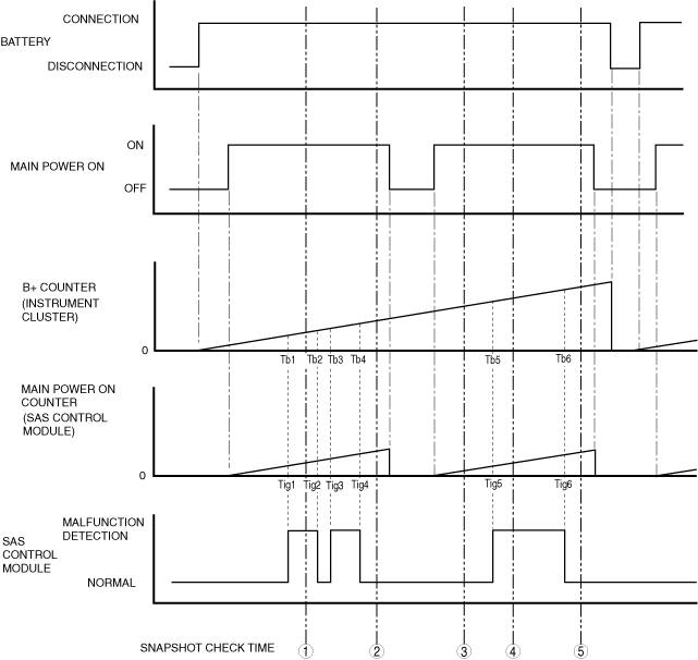
Snapshot counter pattern
a30zzw00000888
|
|
Snap-shot check time |
FAULT_OCCURRENCE_TIMES |
FIRST_FAULT_DETECT |
LAST_FAULT_CLEAR |
LAST_FAULT_CLEAR |
LAST_FAULT_DETECT |
LAST_FAULT_DETECT |
GLOBAL_REAL_TIME |
|---|---|---|---|---|---|---|---|
|
Number of malfunction detections |
Time when initial malfunction occurs (main power ON counter) |
Repair time for last malfunction (B+ counter) |
Repair time for last malfunction (main power ON counter) |
Time when last malfunction occurs (B+ counter) |
Time when last malfunction occurs (main power ON counter) |
Time when first malfunction occurs (B+ counter) |
|
|
1
|
1
|
Tig1
|
―
|
―
|
Tb1
|
Tig1
|
Tb1
|
|
2
|
2
|
Tig1
|
Tb4
|
Tig4
|
Tb3
|
Tig3
|
Tb1
|
|
3
|
2
|
Tig1
|
Tb4
|
Tig4
|
Tb3
|
Tig3
|
Tb1
|
|
4
|
3
|
Tig1
|
Tb4
|
Tig4
|
Tb5
|
Tig5
|
Tb1
|
|
5
|
3
|
Tig1
|
Tb6
|
Tig6
|
Tb5
|
Tig5
|
Tb1
|