 |
a30zzn00001119
ADVANCED KEYLESS ENTRY SYSTEM
id091400703400
Outline
Function
Remote transmitter authorization function
Auto re-lock function
Out-of-area (reception area) type auto lock function
Remote transmitter pause function
Remote transmitter left-in-vehicle prevention function
Alert function
Remote transmitter battery voltage low indication function
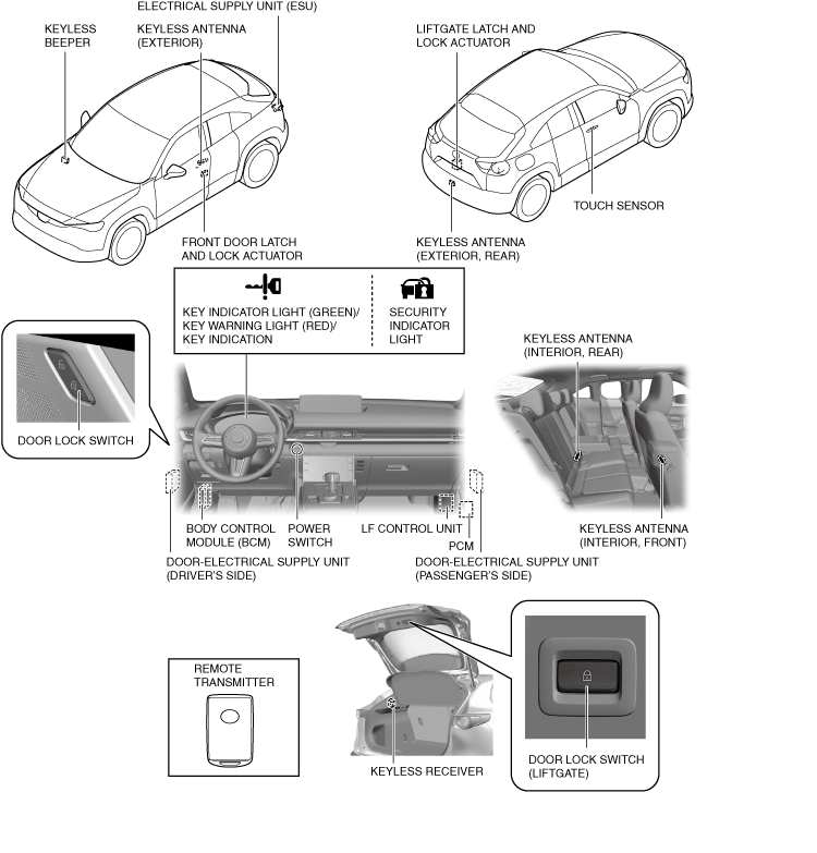
Structural View
a30zzn00001119
|
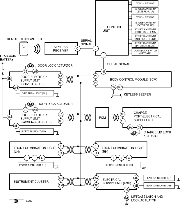
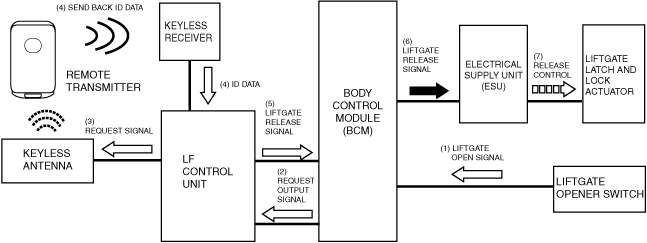
System Wiring Diagram
a30zzn00002275
|
Operation
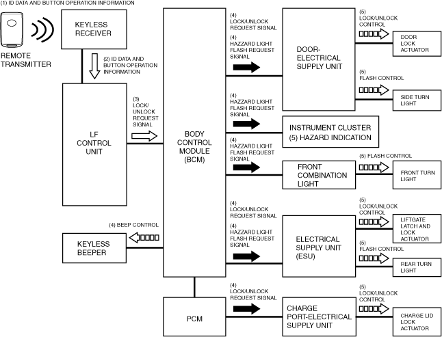
Lock/unlock operation using remote transmitter
1. When the lock button or unlock button on the remote transmitter is pressed, the remote transmitter sends the ID data and button operation information (1) using radio waves.
2. The keyless receiver sends (2) the received ID data and button operation information to the LF control unit via serial communication.
3. When the LF control unit verifies and matches the ID data, it sends a lock/unlock request signal (3) to the body control module (BCM) via serial communication.
4. The body control module (BCM) sends the lock/unlock request signal (4) to the following parts via CAN communication.
5. When the door-electrical supply unit (driver's side) and the door-electrical supply unit (passenger’s side) receive the lock/unlock request signal (4), they operate (5) the motors of the door lock actuators to lock/unlock the doors.
6. When the electrical supply unit (ESU) receives the lock/unlock request signal (4), it operates (5) the motor of the liftgate latch and lock actuator to lock/unlock the liftgate.
7. When the charging port electrical supply unit receives the lock/unlock request signal (4), it operates (5) the charge lid lock actuator to lock/unlock the charging port lid.
8. The body control module (BCM) activates the keyless buzzer*1 (4).
9. The body control module (BCM) sends a hazard light flash request signal (4) to the following parts via CAN communication at the same time the door is locked/unlocked.
10. When the instrument cluster receives the hazard light flash request signal (4), it flashes*1 (5) the hazard warning lights.
11. When the front combination lights receive the hazard light flash request signal (4), they flash the front turn lights*1 (5).
12. When the door-electrical supply unit (driver’s side) and the door-electrical supply unit (passenger’s side) receive the hazard light flash request signal (4), they flash*1 (5) the side turn lights.
13. When the electrical supply unit (ESU) receives the hazard light flash request signal (4), it flashes*1 (5) the rear turn lights.
a30zzn00002276
|
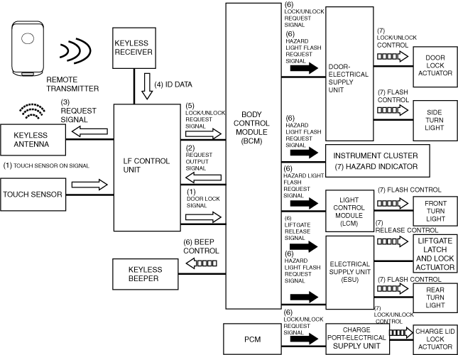
Lock/unlock operation using touch sensor on outer handle
1. When the driver's or the front passenger's touch sensor is touched, a touch sensor on signal (1) is sent from the LF control unit to the body control module (BCM) using SERIAL LFU (UART) communication.
2. Based on the touch sensor on signal, the body control module (BCM) sends a request output signal (2) to the LF control unit using SERIAL LFU (UART) to verify that the remote transmitter is inside the reception area.
3. The LF control unit sends a request signal (3) from the keyless antenna of the door in which the touch sensor was touched to all keyless antennas for the vehicle interior using an electromagnetic wave.
4. The remote transmitter receives the request signal from the outside antenna, and sends ID data (4) to the keyless receiver using an electromagnetic wave.
5. The keyless receiver transmits the received ID data to the LF control unit using SERIAL communication. The LF control unit verifies the key ID number and sends the ID data (5) to the body control module (BCM) using SERIAL LFU (UART) communication.
6. The body control module (BCM) sends the lock/unlock request signal (4) to the door-electrical supply unit (driver's side) and the door-electrical supply unit (passenger's side), and sends a liftgate release request signal (4) to the electrical supply unit (ESU).
7. The PCM sends a charge lid lock/unlock signal (6) to the charge port-electrical supply unit (CP-ESU) via CAN communication.
8. The door-electrical supply unit (driver's side) and the door electrical supply unit (passenger's side) operate (5) the motor of the front door lock actuator to lock/unlock the front doors.
9. The electrical supply unit (ESU) operates the motor of the liftgate latch and lock actuator (5) to release the liftgate.
10. The charge port-electrical supply unit operates (7) the charge lid lock actuator to lock/unlock the charge lid.
11. All the same time as the door lock/unlock operation, the body control module (BCM) sends a hazard light flash request signal (6) to the instrument cluster, the light control module (LCM), the door-electrical supply unit (driver’s side), the door-electrical supply unit (passenger’s side), and the electrical supply unit (ESU) as a CAN signal.
12. The body control module (BCM) operates (6) the keyless beeper for the following number of times:
13. When the instrument cluster, the light control module (LCM), the door-electrical supply unit (driver’s side), the door-electrical supply unit (passenger’s side), and the electrical supply unit (ESU) receive the hazard light flash request signal, the instrument cluster controls (7) the hazard indicator and the light control module (LCM), the door-electrical supply unit (driver’s side), the door-electrical supply unit (passenger’s side), and electrical supply unit (ESU) controls (7) the hazard light.
a30zzn00000308
|
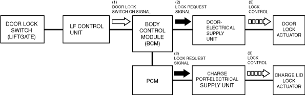
Lock operation using door lock switch (liftgate)
1. When the door lock switch (liftgate) is operated, a door lock switch on signal (1) is sent from the LF control unit to the body control module (BCM) using SERIAL LFU (UART) communication.
2. When the body control module (BCM) receives a door lock switch on signal (1), it determines that the doors are to be locked and sends a lock request signal (2) to the following parts via CAN communication.
3. When the door-electrical supply unit (driver's side) and the door-electrical supply unit (passenger’s side) receive the lock request signal (2), they operate (3) the motor of the front door lock actuator to lock the front doors.
4. When the charging port electrical supply unit receives the lock request signal (2), it operates (3) the charge lid lock actuator to lock/unlock the charging port lid.
a30zzn00001162
|
Liftgate opening operation using liftgate opener switch (exterior)
1. When the liftgate opener switch (exterior) is pressed, a liftgate open signal (1) is input to the body control module (BCM).
2. Based on the liftgate open signal, the body control module (BCM) sends a request output signal (2) to the LF control unit to verify that the remote transmitter is inside the reception area.
3. Based on the request output signal from the body control module (BCM), the LF control unit outputs a request signal (3) using the keyless antenna inside the rear bumper.
4. The remote transmitter receives the request signal from the antenna (outside, rear), and sends ID data (4) to the keyless receiver.
5. The keyless receiver transmits the received ID data (5) to the body control module (BCM).
6. The body control module (BCM) verifies the ID data, and if the ID data matches, it sends a liftgate release signal (6) to the electrical supply unit (ESU).
7. When the electrical supply unit (ESU) receives the liftgate release signal, it operates (7) the liftgate latch and lock actuator motor to release the liftgate.
a30zzn00000310
|
Auto re-lock function operation
Out-of-area (reception area) type auto lock function operation
1. When all doors are closed after any door was opened, the body control module (BCM) goes on auto lock standby if all the following conditions are met.
2. After entering the standby status, if the remote transmitter is moved out of the keyless antenna reception area and the ID data cannot be received from the keyless receiver, the body control module (BCM) sends a lock request signal to the door-electrical supply unit (driver’s side) and the door-electrical supply unit (passenger’s side) to operate all the lock actuators for a lock operation.
Remote transmitter pause function operation
Operation of remote transmitter left-in-vehicle prevention function (during door closing operation)
Operation of remote transmitter left-in-vehicle prevention function (during liftgate closing operation)
Alert function operation
|
Condition |
Keyless beeper |
Instrument cluster |
||
|---|---|---|---|---|
|
Keyless warning alarm |
KEY warning light (red) |
Multi-information display |
||
|
The advanced keyless entry system has a malfunction.
|
―
|
―
|
On
|
 |
|
Driver's door is opened with main power switched to ACC
|
―
|
ON
|
―
|
 |
|
Remote transmitter cannot be detected in vehicle when all doors are closed with main power switched to position other than OFF
|
Sounds 6 times
|
ON
|
Flash
|
 |
|
A door lock operation is performed 3 times within 5 sec using a touch sensor with any door open.
|
Approx. 2 sec
|
―
|
―
|
―
|
Remote transmitter battery voltage low indication function operation
|
Condition |
Instrument cluster |
|
|---|---|---|
|
KEY indicator light (green) |
Multi-information display |
|
|
Body control module (BCM) receives code for low remote transmitter battery voltage*1
|
Flash (for approx. 30 sec after main power is switched OFF)
|
 |