 |
a30zzn00002492
PUSH BUTTON START SYSTEM [(E)]
id0914007035x2
Outline
Function
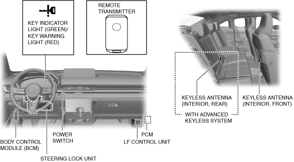
Structural View
a30zzn00002492
|
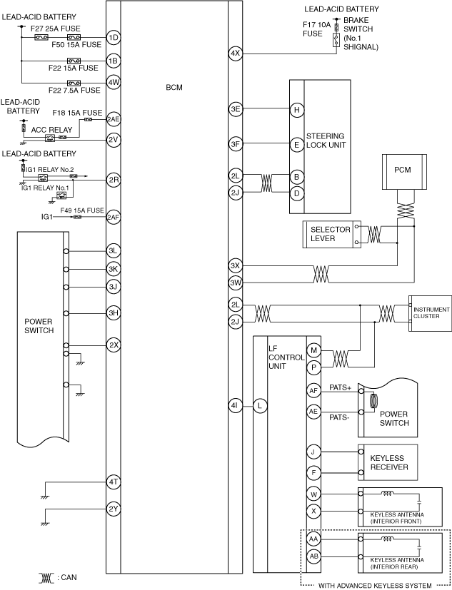
System Wiring Diagram
a30zzn00002493
|
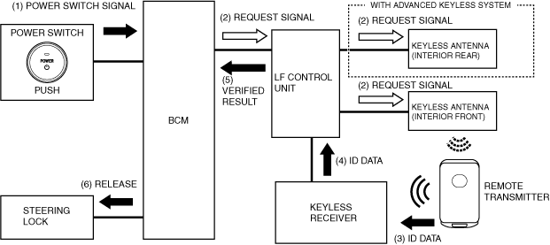
Operation
Remote transmitter verification
1. When the power switch is pressed, a power switch signal (1) is input to the body control module (BCM).
2. When the body control module (BCM) detects a power switch signal, it sends a request signal (2) using all the keyless antennas in the vehicle interior via the LF control unit.
3. The remote transmitter receives the request signal from the interior keyless antennas, and transmits ID data (3) to the keyless receiver.
4. When the keyless receiver receives ID data, it sends (4) the ID data to the LF control unit via serial communication. The LF control unit verifies the ID data, and if the ID data matches, it sends the verified result (5) to the body control module (BCM).
5. The body control module (BCM) releases (6) the steering lock and at the same time switches the power supply to turn the power switch indicator light (amber) on. For details on the power supply switching, refer to the [POWER SUPPLY SWITCHING].(See POWER SUPPLY SWITCHING.)
a30zzn00002494
|
READY on operation
Guidance function
|
Condition |
Multi-information display |
|---|---|
|
Main power is switched from OFF to ON (READY off) without depressing brake pedal
|
 |
|
Power switch is pressed with main power switched ON (READY off) and selector lever not in P position
|
 |
|
Condition |
Instrument cluster |
Power switch |
|||
|---|---|---|---|---|---|
|
KEY indicator light (green) |
KEY warning light (red) |
Multi-information display |
Indicator light (green) |
Indicator light (amber) |
|
|
READY on conditions are met
|
On
|
―
|
―
|
On
|
On
|
|
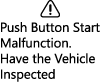
Push Button Start System has a malfunction
|
―
|
―
|
 |
―
|
Flashes
|