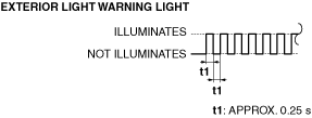
• The flash pattern of the exterior light warning light is as shown in the figure.
a30zzn00000429
|
WARNING/INDICATION/ALARM [LIGHTING SYSTEMS]
id091800707900
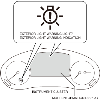
Exterior Light Warning Light/Exterior Light Warning Indication
Purpose
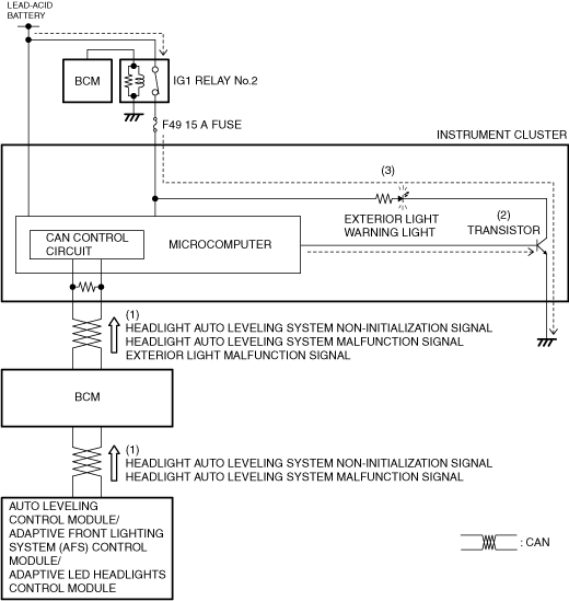
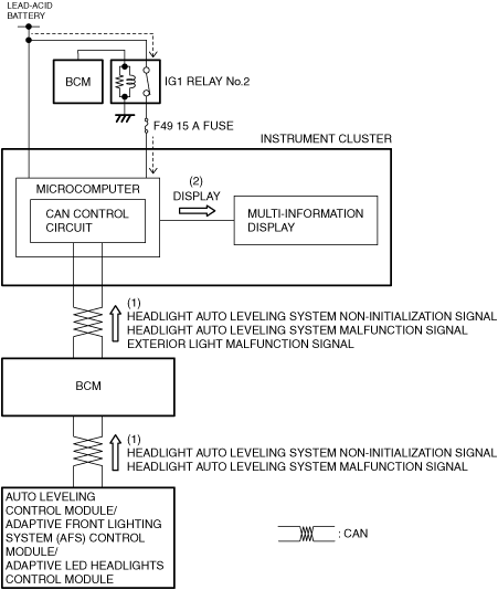
Function
|
Signal name |
Sending module/part name |
Communication method |
Exterior light warning light operation status |
|---|---|---|---|
|
Headlight auto leveling system non-initialization signal
|
Auto leveling control module/adaptive front lighting system (AFS) control module/adaptive LED headlights control module
|
CAN
|
Flash
|
|
Headlight auto leveling system malfunction signal
|
On
|
||
|
Exterior light malfunction signal
|
Body control module (BCM)
|
On
|
a30zzn00000429
|
Structure/Construction
a30zzn00000430
|
Operation
a30zzn00000431
|
a30zzn00000432
|
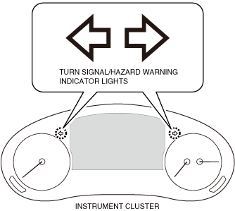
Turn Signal/Hazard Warning Indicator Lights
Purpose
Function
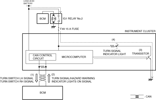
Structure/Construction
a30zzn00000433
|
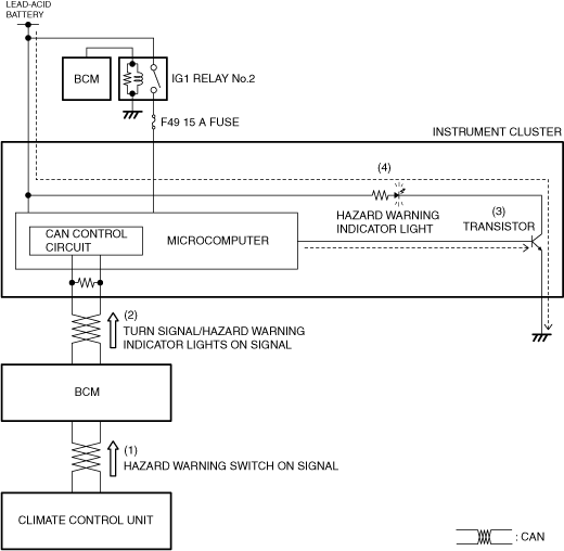
Operation
a30zzn00000434
|
a30zzn00000435
|
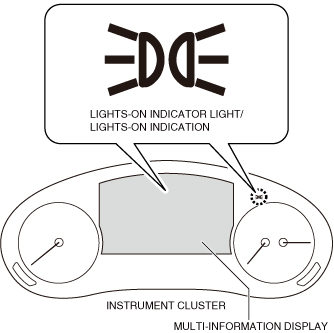
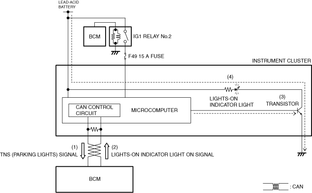
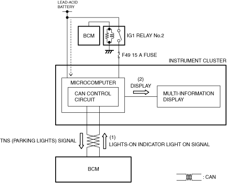
Lights-on Indicator Light/Lights-on Indication
Purpose
Function
Structure/Construction
a30zzn00000437
|
Operation
a30zzn00000438
|
a30zzn00000842
|
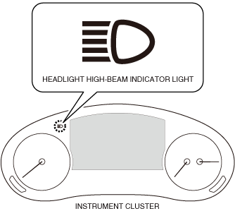
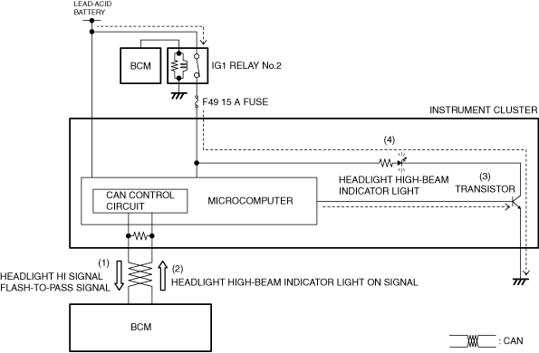
Headlight High-beam Indicator Light
Purpose
Function
Structure/Construction
a30zzn00000440
|
Operation
a30zzn00000441
|
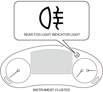
Rear Fog Light Indicator Light
Purpose
Function
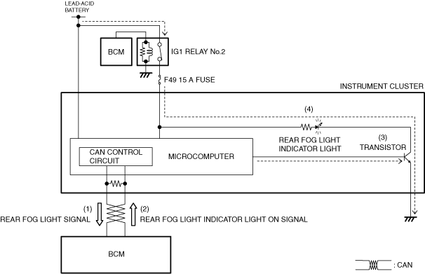
Structure/Construction
a30zzn00000442
|
Operation
a30zzn00000443
|