 |
a30zzn00000444
PARKING ASSIST SYSTEM
id092000703900
Outline
Functions
Fixed assist lines display type
Predicted vehicle path assist lines display type
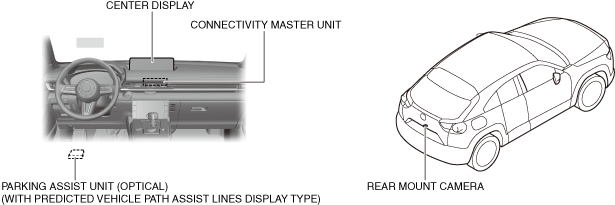
Structure/Construction
System structure
a30zzn00000444
|
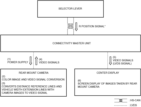
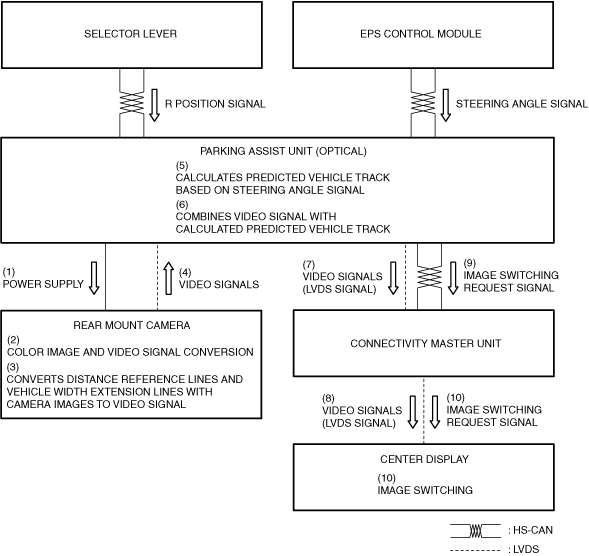
System wiring diagram
a30zzn00000445
|
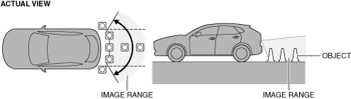
Image Range
a30zzn00000446
|
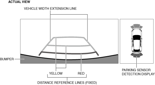
Fixed assist lines display type
a30zzn00000447
|
|
Display item |
Display line color |
Function |
|---|---|---|
|
Distance reference lines (fixed)
|
Red
|
• Shows distance reference line 0.5 m {20 in}from the rear of the rear bumper.
• Not in conjunction with steering operation.
|
|
Yellow
|
• Shows distance reference line 1.0 m {39 in} from the rear of the rear bumper.
• Not in conjunction with steering operation.
|
|
|
Yellow
|
• Shows distance reference line 2.0 m {79 in} from the rear of the rear bumper.
• Not in conjunction with steering operation.
|
|
|
Vehicle width extension line
|
Yellow/Red
|
• Vehicle width extension line. (Including power outer mirror width)
|
|
Parking sensor detection display
|
—
|
• Icon for indicating detection/non-detection of the parking sensor.
|
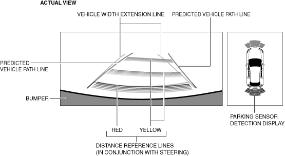
Predicted vehicle path assist lines display type
a30zzn00000448
|
|
Display item |
Display line color |
Function |
|---|---|---|
|
Distance reference line (in conjunction with steering)
|
Red
|
• Shows distance reference line 0.5 m {20 in}from the rear of the rear bumper.
|
|
Yellow
|
• Shows distance reference line 1.0 m {39 in} from the rear of the rear bumper.
|
|
|
Yellow
|
• Shows distance reference line 2.0 m {79 in} from the rear of the rear bumper.
|
|
|
Vehicle width extension line
|
Blue
|
• Vehicle width extension line. (Including power outer mirror width)
|
|
Predicted vehicle path line
|
Yellow
|
• Calculated vehicle path based on steering angle signal.
|
|
Parking sensor detection display
|
—
|
• Icon for indicating detection/non-detection of the parking sensor.
|
Operation
Fixed assist lines display type
a30zzn00000449
|
Predicted vehicle path assist lines display type
a30zzn00000450
|