 |
a30zzw00001764
EMERGENCY CALL SWITCH INSPECTION [(E)]
id0922007061x2
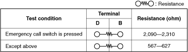
Switch Inspection
1. Disconnect the negative lead-acid battery terminal. (See NEGATIVE LEAD-ACID BATTERY TERMINAL DISCONNECTION/CONNECTION.)
2. Remove the front map light. (See FRONT MAP LIGHT REMOVAL/INSTALLATION [(E)].)
3. Verify that the continuity is as indicated in the table.
a30zzw00001764
|
a30zzw00001765
|
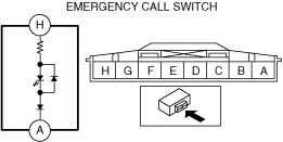
LED Illumination Inspection
1. Disconnect the negative lead-acid battery terminal. (See NEGATIVE LEAD-ACID BATTERY TERMINAL DISCONNECTION/CONNECTION.)
2. Remove the front map light. (See FRONT MAP LIGHT REMOVAL/INSTALLATION [(E)].)
3. Apply lead-acid battery positive voltage to emergency call switch terminal H, and connect terminal A to ground.
a30zzw00001766
|
4. Verify that the LED illuminates.
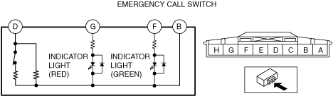
Indicator Light Illumination Inspection
1. Disconnect the negative lead-acid battery terminal. (See NEGATIVE LEAD-ACID BATTERY TERMINAL DISCONNECTION/CONNECTION.)
2. Remove the front map light. (See FRONT MAP LIGHT REMOVAL/INSTALLATION [(E)].)
3. Prepare three dry cell batteries (1.5 V).
4. Connect the three dry cell batteries in a series.
5. Connect the positive pole of the dry cell battery and the negative pole of the dry cell battery to each terminal of the emergency call switch as indicated in the table below, and verify that each LED turns on normally.
a30zzw00001764
|
|
Dry cell battery positive pole terminal |
Dry cell battery negative pole terminal |
Condition |
|
|---|---|---|---|
|
Indicator light (red) |
Indicator light (green) |
||
|
G
|
B
|
Turns ON
|
Turns OFF
|
|
F
|
B
|
Turns OFF
|
Turns ON
|