 |
a30zzb00000168
SIDE SILL PANEL INSTALLATION [PANEL REPLACEMENT]
id098008615200
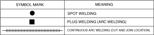
Symbol Mark
a30zzb00000168
|
Installation Procedure
Side Sill (Front-side)
1. When installing new parts, measure and adjust the body as necessary to conform with standard dimensions.
2. Drill holes for the plug welding before installing the new parts.
3. After temporarily installing new parts, make sure the related parts fit properly.
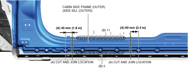
4. Cut and join the part to area A shown in the figure.
5. Plug welds in the 14 locations in area B shown in the figure and install the cabin side frame (outer) (side sill (outer)).
a30zzb00000169
|
Side sill component
1. When installing new parts, measure and adjust the body as necessary to conform with standard dimensions.
2. Drill holes for the plug welding before installing the new parts.
3. After temporarily installing new parts, make sure the related parts fit properly.
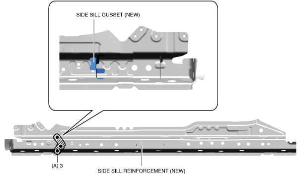
4. Drill the spot welds in the 3locations in area A of the new part shown in the figure and remove the side sill reinforcement (rear) and side sill gusset.
a30zzb00000170
|
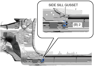
5. Plug welds in the 2 locations in area B shown in the figure and install the side sill gusset.
a30zzb00000171
|
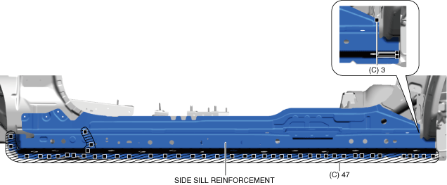
6. Plug welds in the 50 locations in the area C shown in the figure and install the side sill reinforcement.
a30zzb00000172
|
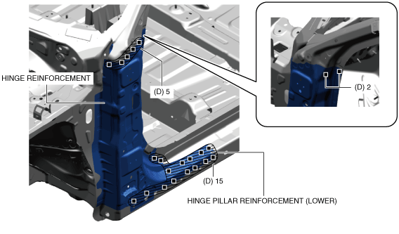
7. Plug welds in the 22 locations in area D shown in the figure and install the hinge reinforcement (lower) and hinge pillar reinforcement (lower).
a30zzb00000173
|
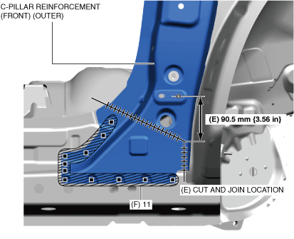
8. Cut and join the location in area E shown in the figure.
9. Plug welds in the 11 locations in area F shown in the figure and install the C-pillar reinforcement (front) (outer).
a30zzb00000174
|
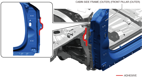
10. Apply the adhesives to the positions shown in the figure.
|
Recommended agent |
Handleability time (minute) |
Hardening time (minute) |
|---|---|---|
|
ThreeBond 2088E
|
70
|
• 25°C {77°F}:1,440
• 120°C {248°F}:60
|
|
3M Panel Bonding Adhesive PN 8115
|
45
|
• 25°C {77°F}:1,440
• 60°C {140°F}:90
|
a30zzb00000163
|
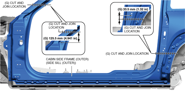
11. Cut and join the 2 locations in area G shown in the figure.
a30zzb00000175
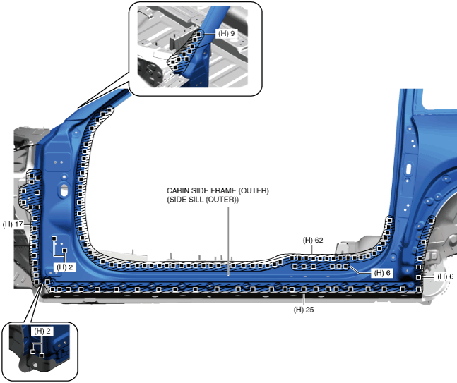
|
12. Plug welds in the 129 locations in area H shown in the figure and install the cabin side frame (outer) (side sill (outer)).
a30zzb00000176
|
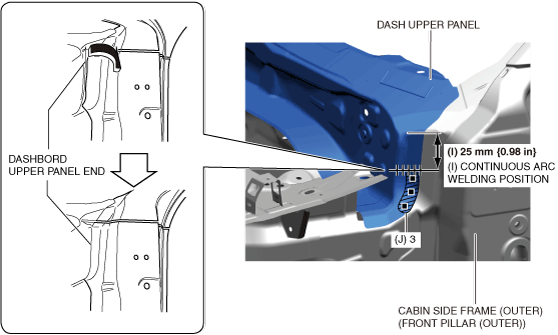
13. Repair the end of the dash upper panel in the direction of the arrow shown in the figure.
14. Continuous arc weld area I shown in the figure.
15. Plug welds in the 3 locations in area J shown in the figure.
a30zzb00000177
|