 |
a30zzb00000025
SIDE SILL PANEL REMOVAL [PANEL REPLACEMENT]
id098008615300
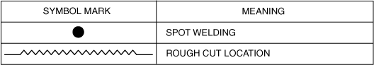
Symbol Mark
a30zzb00000025
|
Removal Procedure
Side sill (front)
1. Refer to [DAMAGED VEHICLE HANDLING] and [HIGH VOLTAGE SERVICE CAUTIONS] in the general information, implement the necessary measures, and then start the procedure.(See DAMAGED VEHICLE HANDLING [(E)].) (See HIGH VOLTAGE SERVICE CAUTIONS.)
2. Rough cut the 2 locations in area A shown in the figure.
3. Drill the spot welds in the 14 locations in area B shown in the figure.
a30zzb00000050
|
4. Remove the cabin side frame (outer) (side sill (outer)).
Side sill component
1. After referring to [HIGH VOLTAGE SERVICE CAUTIONS] in the general information, implement the necessary measures and then start the procedure. (See HIGH VOLTAGE SERVICE CAUTIONS.)
2. Rough cut the 2 locations in area A shown in the figure.
a30zzb00000053
|
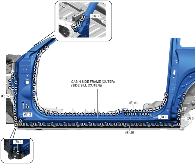
3. Drill the spot welds in the 127 locations in area B shown in the figure.
am6zzb00000359
|
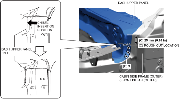
4. Rough cut the location in area C shown in the figure.
5. Drill the spot welds in the 3 locations in area D shown in the figure.
6. Insert a chisel into the position of the arrow shown in the figure, peel off the adhesive, and then move the end of the dash upper panel.
a30zzb00000052
|
7. Remove the cabin side frame (outer) (side sill (outer)).
8. Rough cut the location in area E shown in the figure.
9. Drill the spot welds in the 11 locations in area F shown in the figure.
a30zzb00000054
|
10. Remove the C-pillar reinforcement (front) (outer).
11. Drill the spot welds in the 22 locations in area G shown in the figure.
a30zzb00000055
|
12. Remove the hinge reinforcement and hinge reinforcement (lower) at the same time.
13. Drill the spot welds in the 47 locations in area H shown in the figure.
a30zzb00000056
|
14. Remove the side sill reinforcement.
15. Drill the spot welds in the 2 locations in area I shown in the figure.
a30zzb00000057
|
16. Remove the side sill gusset.