 |
a30zzw00006534
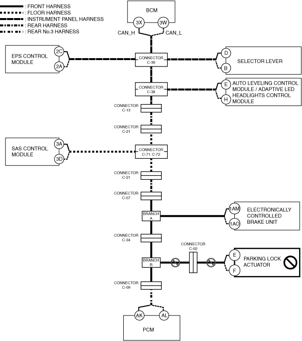
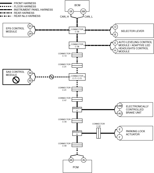
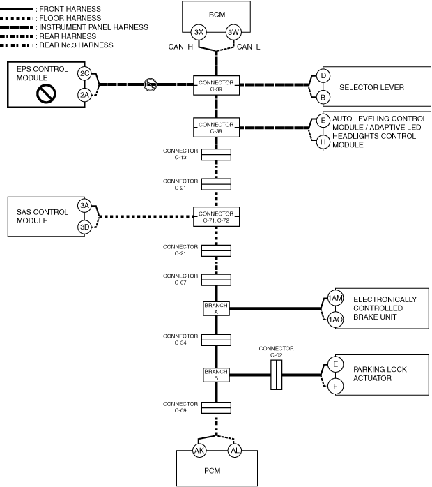
DETERMINING OPEN CIRCUIT LOCATION (CAN-BUS No.1) [R.H.D.]
id100226001700
1. Verify the CAN system-related module DTCs and the module displayed in red or blue on the M-MDS screen.
2. Apply the communication error DTC and the module displayed in red or blue to the DTC output pattern and malfunctioning location, and select the possible cause for the diagnostic result and the reference for the inspection item. (See DTC Output Pattern And Malfunctioning Location.)
3. Inspect the possible cause and inspection item of the applicable malfunctioning part.
DTC Output Pattern And Malfunctioning Location
|
M-MDS display |
DTC |
DTC output pattern and malfunctioning location |
|||||||||||
|---|---|---|---|---|---|---|---|---|---|---|---|---|---|
|
DTC output module |
|||||||||||||
|
PCM (e-SKYACTIV)
|
U0100:00
|
||||||||||||
|
U0103:00
|
×
|
||||||||||||
|
U0121:00
|
×
|
||||||||||||
|
U0129:00
|
×
|
||||||||||||
|
U0131:00
|
×
|
||||||||||||
|
U0140:00
|
×
|
||||||||||||
|
U0151:00
|
×
|
×
|
|||||||||||
|
U0155:00
|
|||||||||||||
|
U0156:00
|
|||||||||||||
|
U0164:00
|
|||||||||||||
|
U016B:00
|
|||||||||||||
|
U01BA:00
|
×
|
||||||||||||
|
U0291:00
|
×
|
||||||||||||
|
U102D:00
|
×
|
||||||||||||
|
U2121:00
|
|||||||||||||
|
U212E:00
|
|||||||||||||
|
U2131:00
|
|||||||||||||
|
U2133:00
|
|||||||||||||
|
Parking lock actuator
|
U0100:00
|
×
|
|
|
|
|
|
|
|
|
|
|
|
|
U0115:00
|
×
|
|
|
|
|
|
|
|
|
|
|
|
|
|
U0100:41
|
×
|
|
|
|
|
|
|
|
|
|
|
|
|
|
U0100:82
|
×
|
|
|
|
|
|
|
|
|
|
|
|
|
|
Electronically controlled brake unit
|
U0100:00
|
×
|
|
×
|
|||||||||
|
U0131:00
|
×
|
||||||||||||
|
U0140:00
|
×
|
||||||||||||
|
U0151:00
|
×
|
||||||||||||
|
U0155:00
|
|||||||||||||
|
U0164:00
|
|||||||||||||
|
U2121:00
|
|||||||||||||
|
U212E:00
|
|||||||||||||
|
U2131:00
|
|||||||||||||
|
SAS control module
|
U0140:00
|
|
|
|
|
|
|
|
|
|
|
|
×
|
|
U0155:00
|
|
|
|
|
|
|
|
|
|
|
|
|
|
|
U0155:41
|
|
|
|
|
|
|
|
|
|
|
|
|
|
|
U0155:82
|
|
|
|
|
|
|
|
|
|
|
|
|
|
|
U0156:00
|
|
|
|
|
|
|
|
|
|
|
|
|
|
|
U0156:41
|
|
|
|
|
|
|
|
|
|
|
|
|
|
|
U0156:82
|
|
|
|
|
|
|
|
|
|
|
|
|
|
|
Auto leveling control module
|
U0122:87
|
×
|
×
|
×
|
|||||||||
|
U212A:87
|
|||||||||||||
|
U212B:87
|
×
|
||||||||||||
|
U212D:87
|
|||||||||||||
|
Adaptive LED headlights control module
|
U0122:87
|
×
|
×
|
×
|
|||||||||
|
U0126:87
|
|||||||||||||
|
U0155:87
|
|||||||||||||
|
U2121:87
|
|||||||||||||
|
U212A:87
|
|||||||||||||
|
U212B:87
|
×
|
||||||||||||
|
U212D:87
|
|||||||||||||
|
Selector lever
|
U0100:00
|
×
|
×
|
×
|
×
|
×
|
|||||||
|
U0121:00
|
×
|
×
|
×
|
×
|
|||||||||
|
U0140:00
|
×
|
||||||||||||
|
U212B:00
|
×
|
||||||||||||
|
EPS control module
|
U0100:00
|
×
|
×
|
×
|
×
|
×
|
|||||||
|
U0121:00
|
×
|
×
|
×
|
×
|
|||||||||
|
U0140:00
|
×
|
||||||||||||
|
U2121:00
|
×
|
||||||||||||
|
Vehicle control module (VCM)
|
U0100:00
|
×
|
×
|
×
|
×
|
×
|
×
|
||||||
|
U0101:00
|
×
|
×
|
|||||||||||
|
U0121:00
|
×
|
×
|
×
|
×
|
×
|
||||||||
|
U0126:00
|
|||||||||||||
|
U0131:00
|
×
|
×
|
|||||||||||
|
U0140:00
|
×
|
||||||||||||
|
U0151:00
|
×
|
×
|
×
|
×
|
|||||||||
|
U0155:00
|
|||||||||||||
|
U0156:00
|
|||||||||||||
|
U0164:00
|
|||||||||||||
|
U2120:00
|
|||||||||||||
|
U2122:00
|
|||||||||||||
|
U2123:00
|
|||||||||||||
|
U2125:00
|
|||||||||||||
|
U2126:00
|
|||||||||||||
|
U212E:00
|
|||||||||||||
|
U2131:00
|
|||||||||||||
|
U2132:00
|
|||||||||||||
|
U2133:00
|
|||||||||||||
|
U2139:00
|
|||||||||||||
|
U213A:00
|
|||||||||||||
|
Body control module (BCM)
|
U0100:00
|
×
|
×
|
×
|
×
|
×
|
×
|
||||||
|
U0101:00
|
×
|
×
|
×
|
×
|
×
|
×
|
|||||||
|
U0103:00
|
×
|
×
|
|||||||||||
|
U0103:87
|
×
|
×
|
|||||||||||
|
U0111:00
|
|||||||||||||
|
U0115:00
|
×
|
×
|
×
|
×
|
×
|
×
|
|||||||
|
U0121:00
|
×
|
×
|
×
|
×
|
×
|
||||||||
|
U0121:87
|
×
|
×
|
×
|
×
|
×
|
||||||||
|
U0126:00
|
|||||||||||||
|
U0131:00
|
×
|
×
|
|||||||||||
|
U0151:00
|
×
|
×
|
×
|
×
|
|||||||||
|
U0155:00
|
|||||||||||||
|
U0156:00
|
|||||||||||||
|
U0158:00
|
|||||||||||||
|
U0164:00
|
|||||||||||||
|
U016B:00
|
|||||||||||||
|
U0182:00
|
×
|
×
|
×
|
||||||||||
|
U0198:00
|
|||||||||||||
|
U01BA:00
|
×
|
×
|
×
|
×
|
×
|
×
|
|||||||
|
U2121:49
|
|||||||||||||
|
U212A:00
|
|||||||||||||
|
U212D:00
|
|||||||||||||
|
U212E:00
|
|||||||||||||
|
U2131:00
|
|||||||||||||
|
U2133:00
|
|||||||||||||
|
U2135:00
|
|||||||||||||
|
U213A:00
|
|||||||||||||
|
U213B:00
|
|||||||||||||
|
U213C:00
|
×
|
×
|
×
|
×
|
×
|
||||||||
|
U2147:00
|
|||||||||||||
|
Dash-electrical supply unit
|
U0100:00
|
×
|
×
|
×
|
×
|
×
|
×
|
||||||
|
U0121:00
|
×
|
×
|
×
|
×
|
×
|
||||||||
|
U0140:00
|
×
|
||||||||||||
|
U0151:00
|
×
|
×
|
×
|
×
|
|||||||||
|
U0156:00
|
|||||||||||||
|
U016B:00
|
|||||||||||||
|
U212E:00
|
|||||||||||||
|
U2131:00
|
|||||||||||||
|
U2133:00
|
|||||||||||||
|
U213A:00
|
|||||||||||||
|
Heat pump control unit
|
U2133:00
|
|
|
|
|
|
|
|
|
|
|
|
|
|
U0140:00
|
|
|
|
|
|
|
|
|
|
|
|
×
|
|
|
U0164:00
|
|
|
|
|
|
|
|
|
|
|
|
|
|
|
Connectivity master unit (CMU)
|
U0101:00
|
×
|
×
|
||||||||||
|
U0131:00
|
×
|
×
|
|||||||||||
|
U0140:00
|
×
|
||||||||||||
|
U0151:00
|
×
|
×
|
×
|
×
|
|||||||||
|
U0155:00
|
|||||||||||||
|
U0198:00
|
|||||||||||||
|
U2121:00
|
|||||||||||||
|
U213C:00
|
×
|
×
|
×
|
×
|
×
|
||||||||
|
U213E:00
|
×
|
×
|
×
|
×
|
×
|
×
|
|||||||
|
Emergency call unit
|
U0140:00
|
×
|
|||||||||||
|
U0151:00
|
×
|
×
|
×
|
×
|
|||||||||
|
U0164:00
|
|||||||||||||
|
U213C:00
|
×
|
×
|
×
|
×
|
×
|
||||||||
|
Approaching vehicle audible system device
|
U0101:00
|
×
|
×
|
||||||||||
|
U0121:00
|
×
|
×
|
×
|
×
|
×
|
||||||||
|
M-MDS display module
|
Module displayed in red or blue
|
||||||||||||
|
PCM (e-SKYACTIV)
|
×
|
|
×
|
|
×
|
|
×
|
|
×
|
|
|
×
|
|
|
Parking lock actuator
|
|
×
|
×
|
|
×
|
|
×
|
|
×
|
|
|
×
|
|
|
Electronically controlled brake unit
|
|
|
|
×
|
×
|
|
×
|
|
×
|
|
|
×
|
|
|
SAS control module
|
|
|
|
|
|
×
|
×
|
|
×
|
|
|
×
|
|
|
Auto leveling control module / adaptive LED headlights control module
|
|
|
|
|
|
|
|
×
|
×
|
|
|
×
|
|
|
EPS control module
|
|
|
|
|
|
|
|
|
|
×
|
|
×
|
|
|
Selector lever
|
|
|
|
|
|
|
|
|
|
|
×
|
×
|
|
|
Diagnostic result
|
|||||||||||||
|
Possible cause and inspection item
|
|||||||||||||
A
Possible cause
System wiring diagram
a30zzw00006534
|
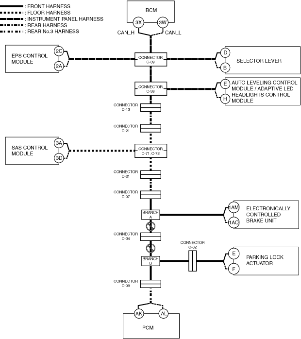
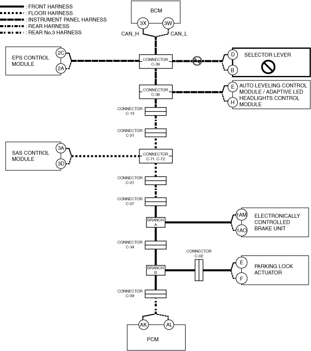
B
Possible cause
System wiring diagram
a30zzw00006535
|
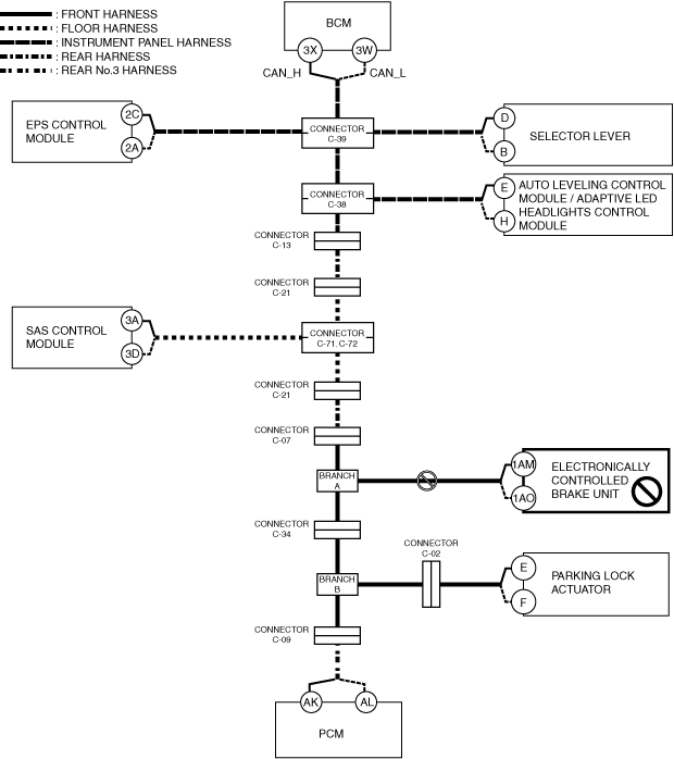
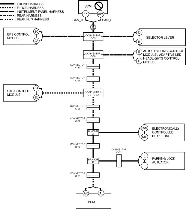
C
Possible cause
System wiring diagram
a30zzw00006536
|
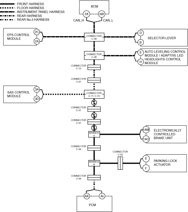
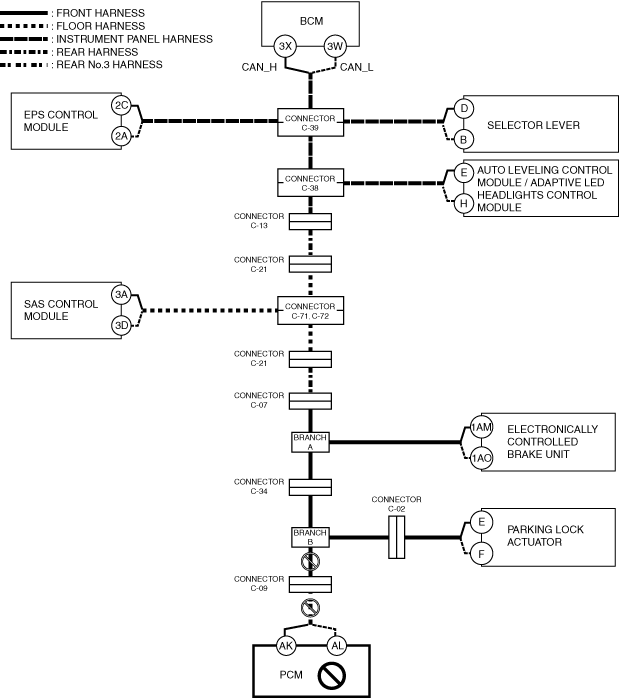
D
Possible cause
System wiring diagram
a30zzw00006537
|
E
Possible cause
System wiring diagram
a30zzw00006538
|
F
Possible cause
System wiring diagram
a30zzw00006539
|
Inspection item
G
Possible cause
System wiring diagram
a30zzw00006540
|
Inspection item
H
Possible cause
System wiring diagram
a30zzw00006541
|
Inspection item
I
Possible cause
System wiring diagram
a30zzw00006542
|
Inspection item
J
Possible cause
System wiring diagram
a30zzw00006544
|
Inspection item
K
Possible cause
System wiring diagram
a30zzw00006543
|
Inspection item
L
Possible cause
System wiring diagram
a30zzw00006545
|
Inspection item